DUCATI DESMOTO
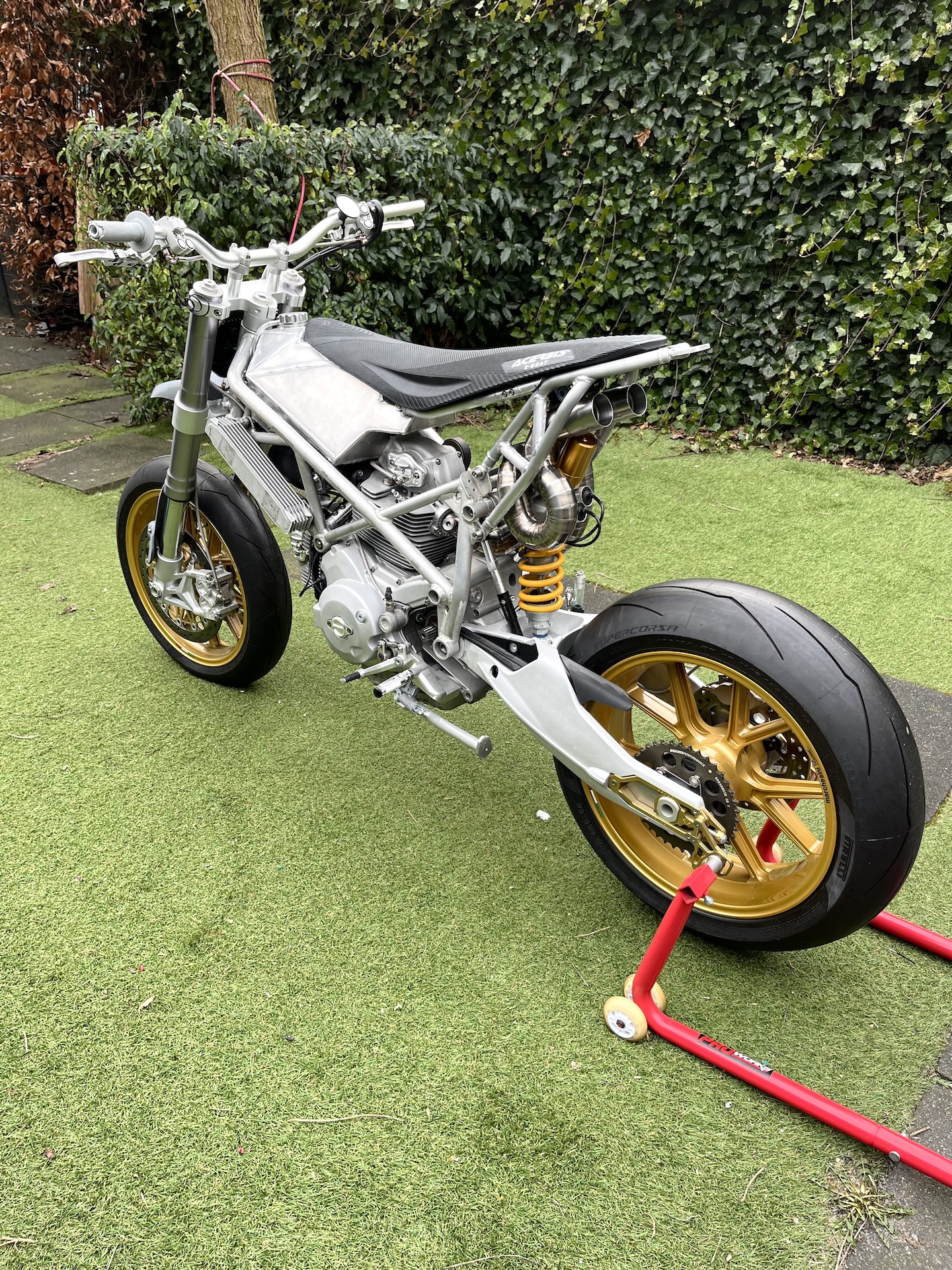
My personal vision of the ultimate Ducati Supermotard with the perfect balance between function and form. An extremely lightweight, high performance machine that wants to buck you off with every twist of the throttle…
Built from Titanium, Magnesium, Aluminium, and Nylon Carbon Fiber. Over 2000 hours of design and fabrication spread across 5.5 years.
End result?! 141KG WET, 112HP and 123NM torque on the rear wheel. Insanity!
My previous project allowed me to start a “internship” & amazing friendship at Biggelaar Special Performance. Over there I learned the more intricate stuff like engine revisions, tuning / flowing cylinder heads, ECU / Dyno remapping etc. This allowed me to elevate this build to a next level compared to the previous project!
Ducati Desmoto is featured on “BikeExif“, “RevZilla“, “MCN” and the magazines “KicXStart” and “Motorrijder”!
DUCATI DESMOTO
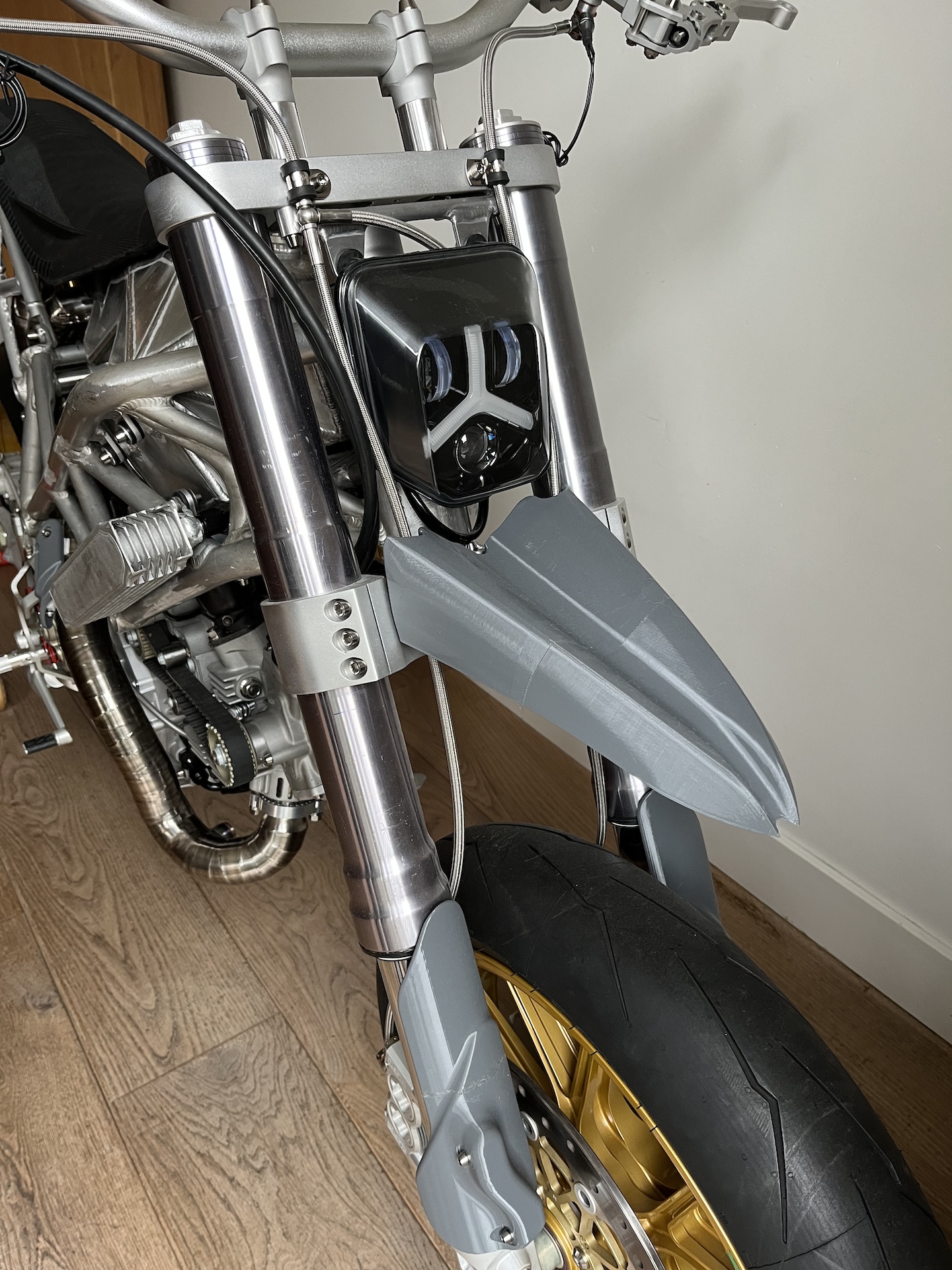
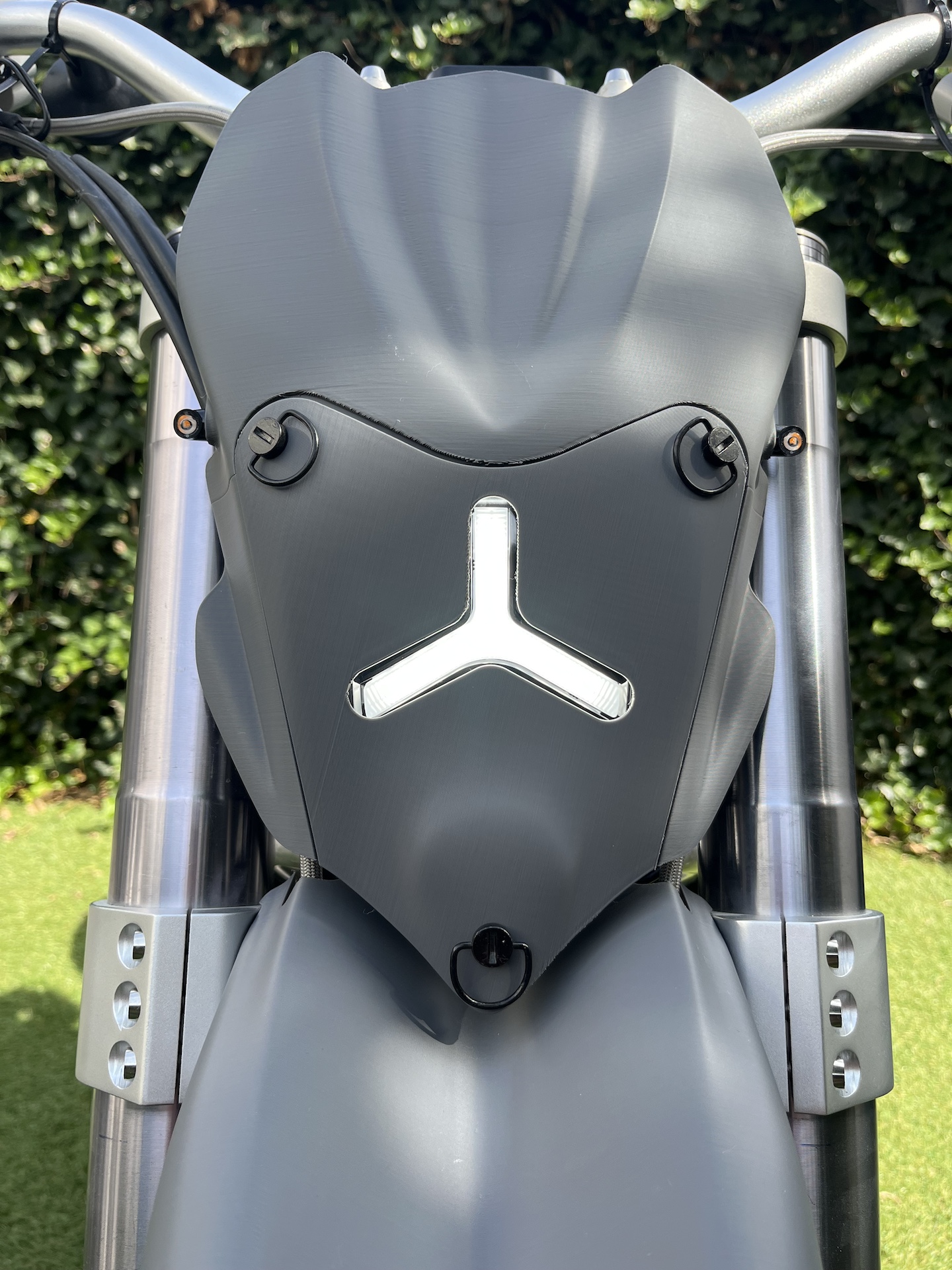
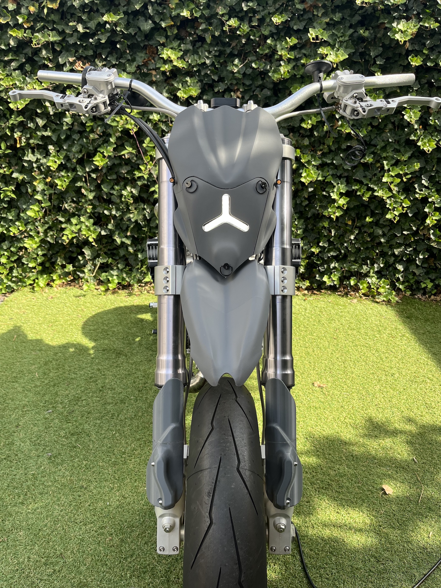
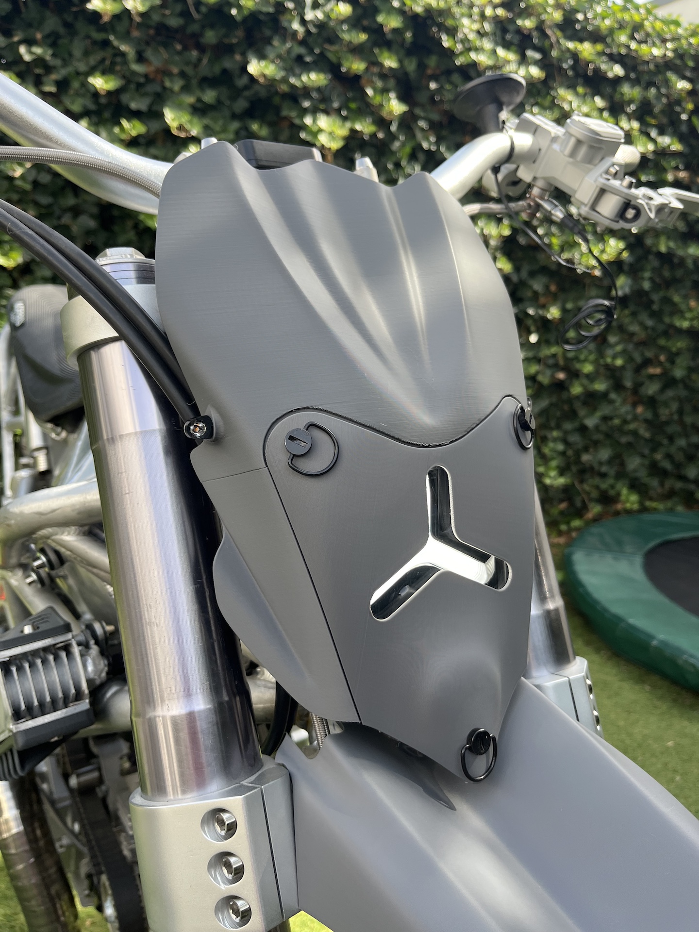
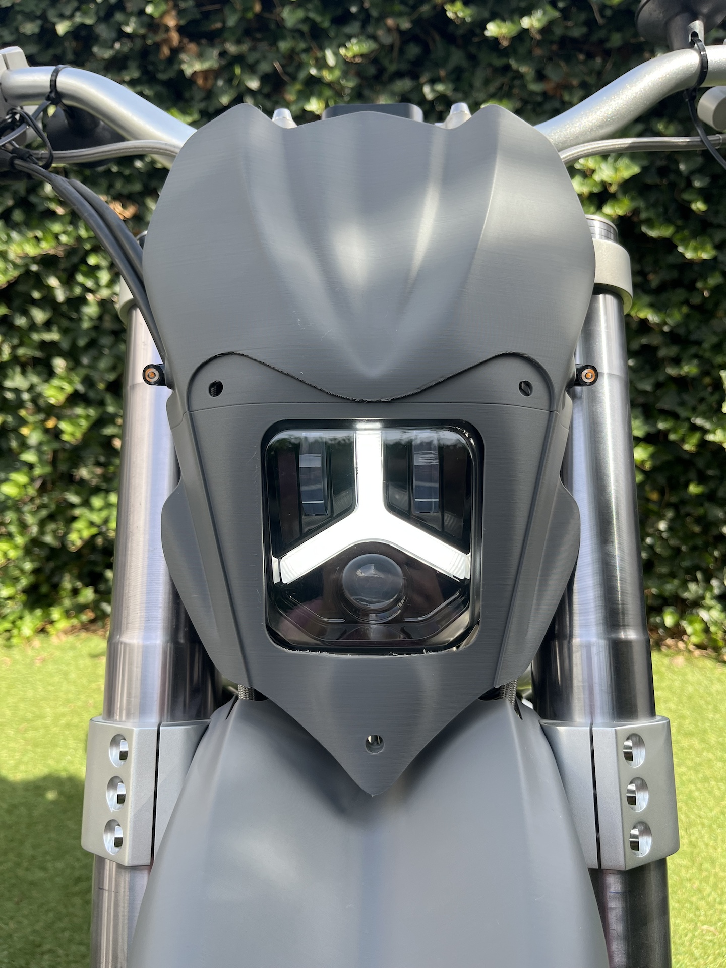
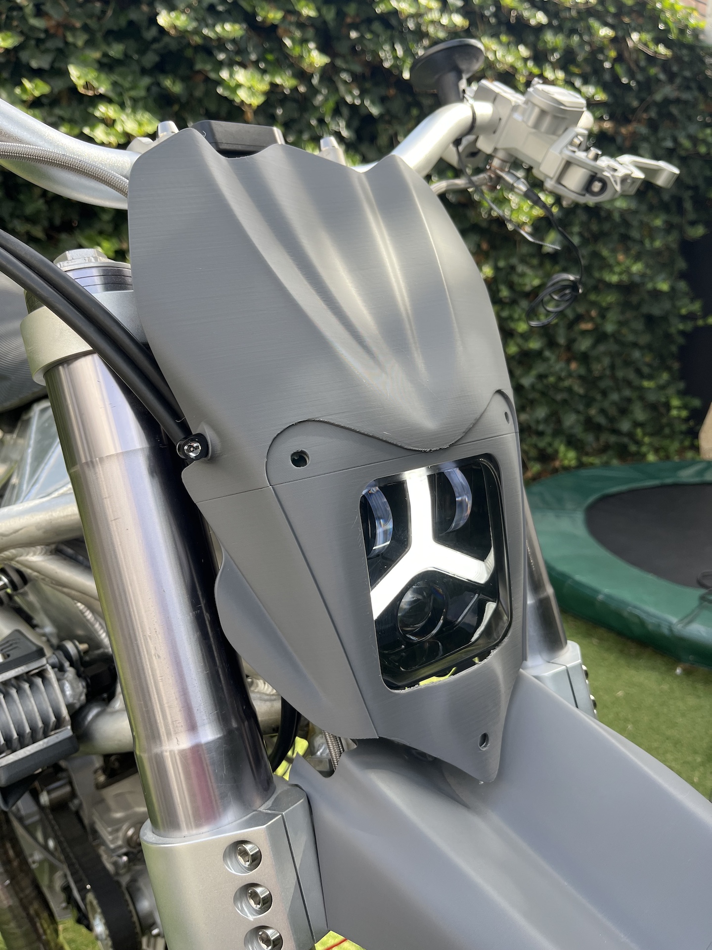
HEADLIGHT FRONT FAIRING
Project Desmoto front fairing DONE! With a removable headlight shield that only shows the LED DRL strip.
Practical, not sure. Unique, 100%!
Will be fabricated out of carbon when all the parts for the bike are designed.
Took “only” 2.5 weeks to design, 9x 3D printed prototypes and the CAD file is up to version 106…. This took allot of my CAD and creative skills.
Taste is subjective obviously, but I am extremely happy with the end result! Almost exactly as I imagined it 2/3 years ago when I bought the headlight.
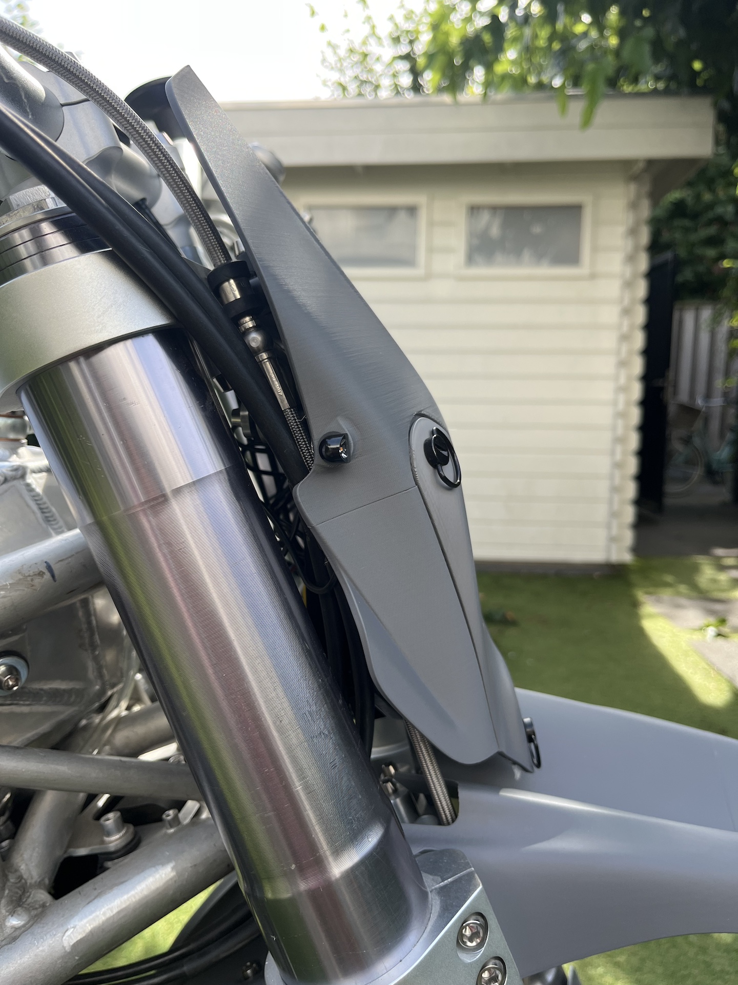
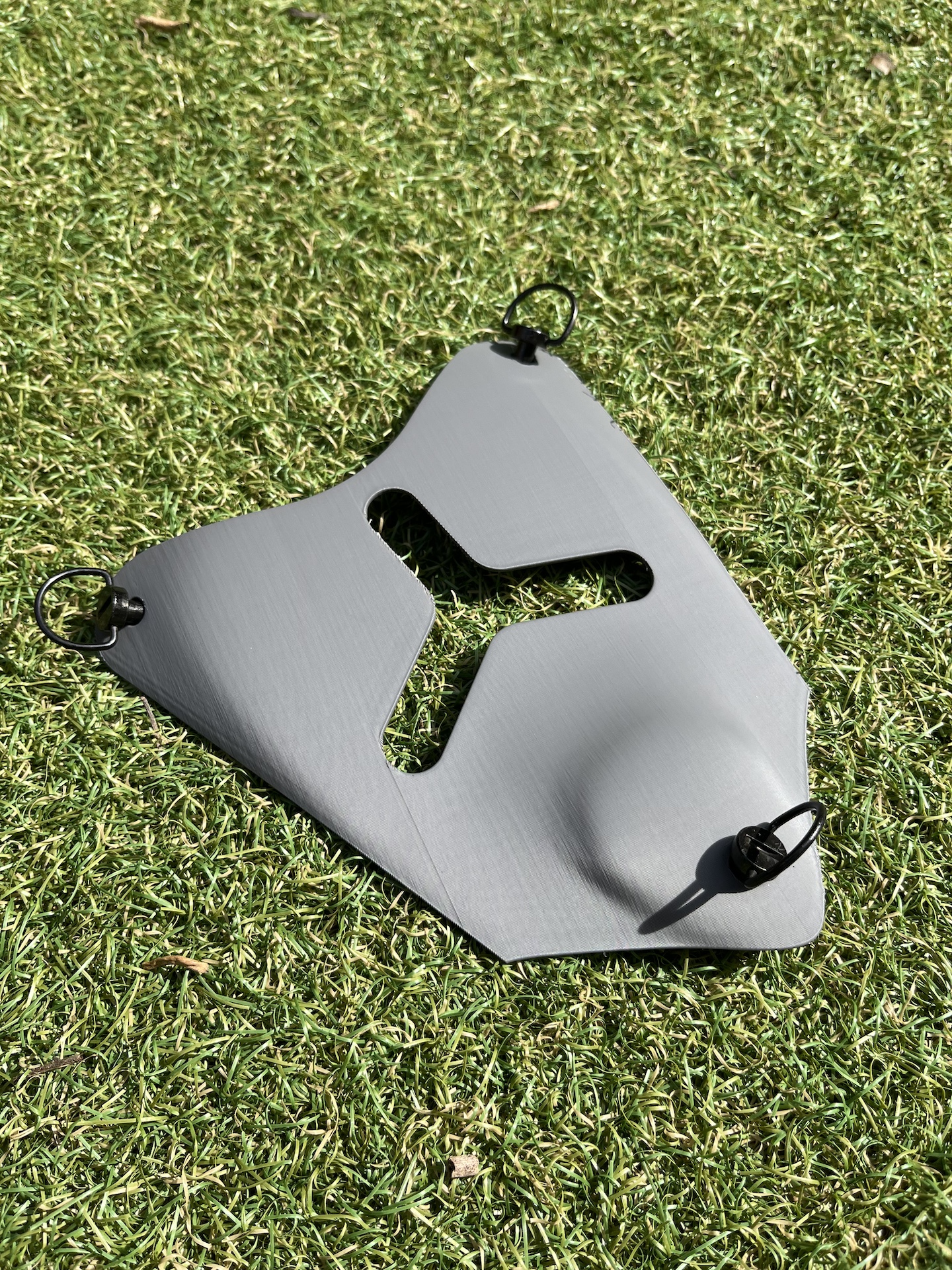
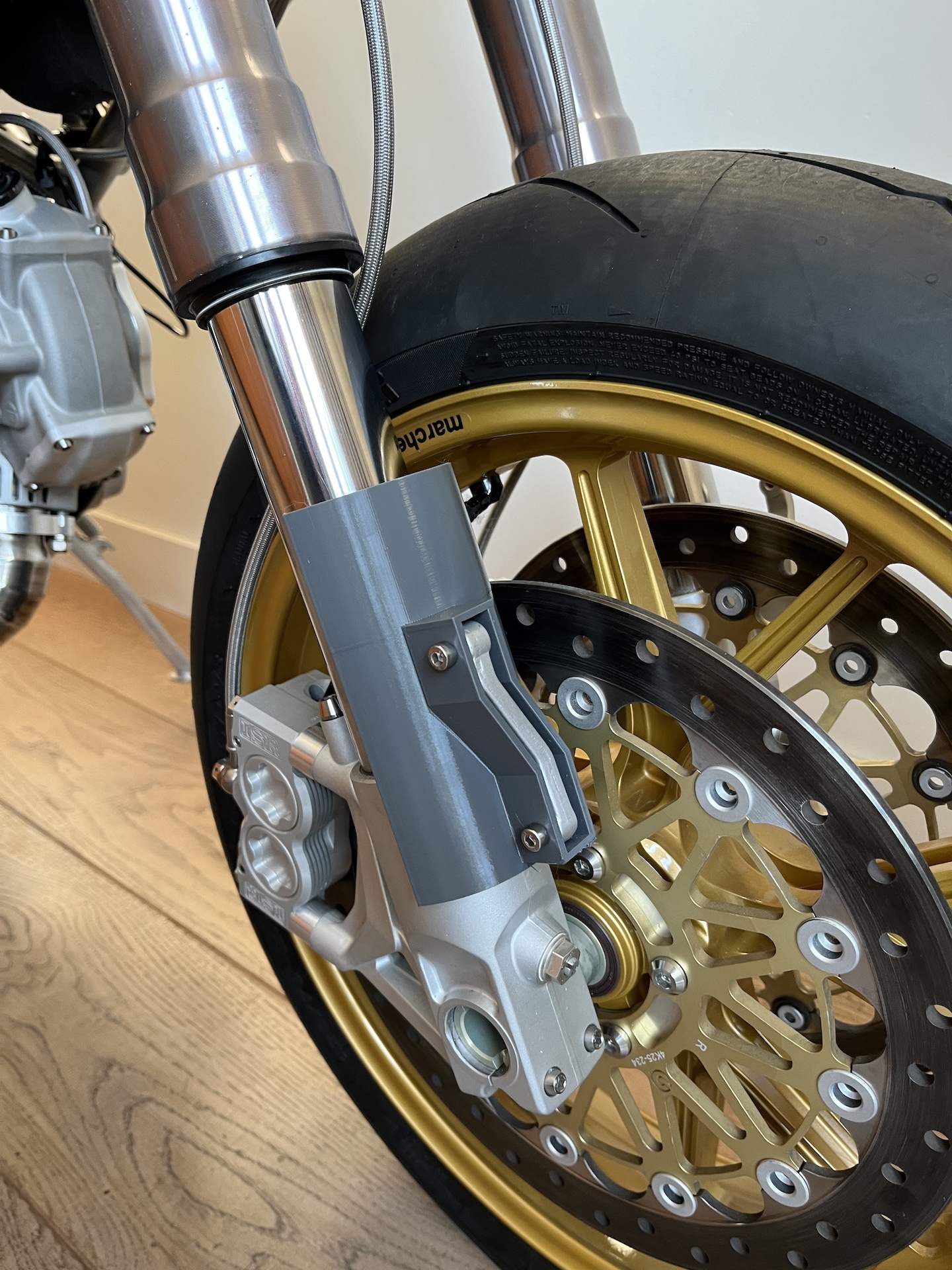
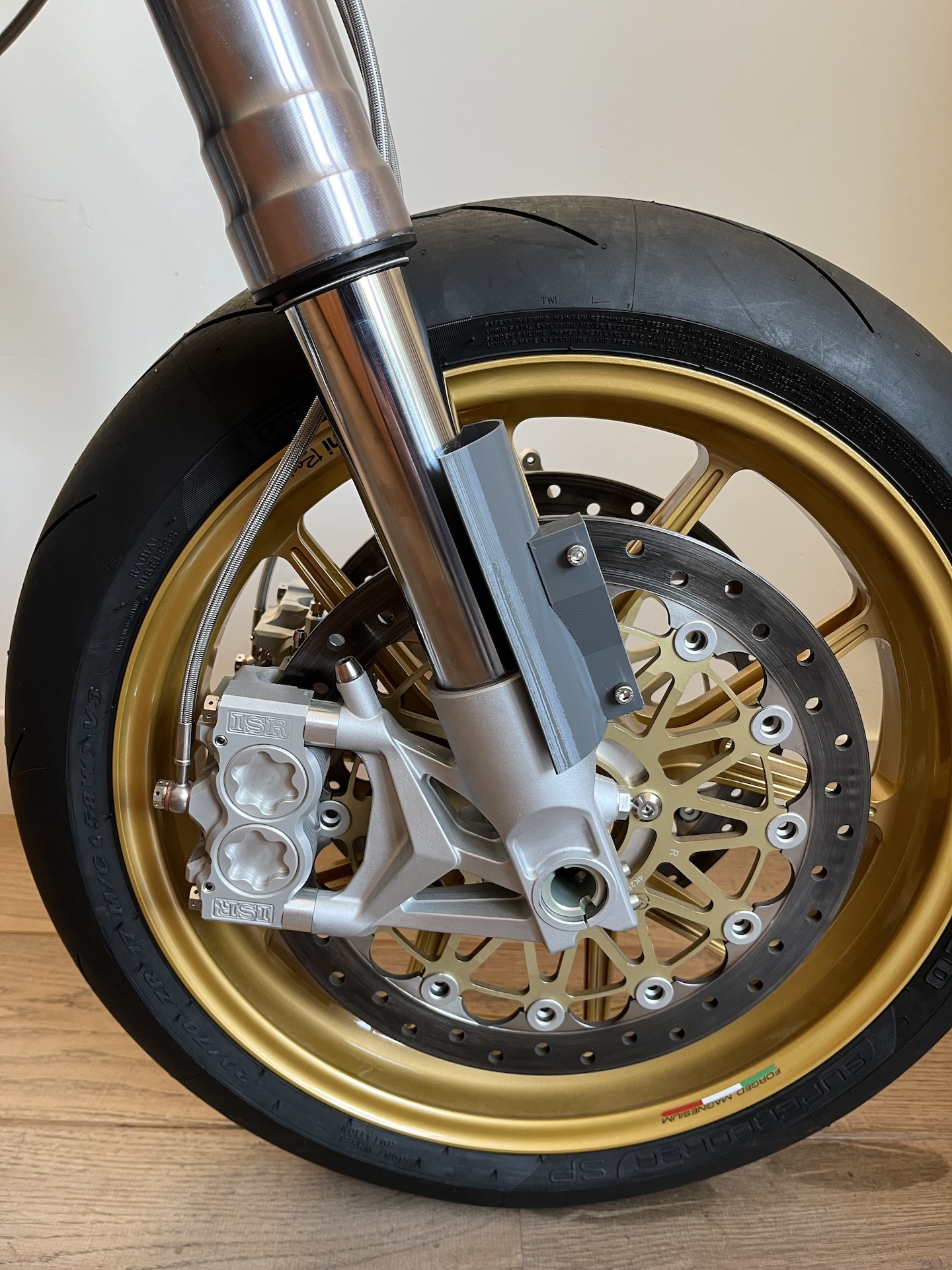
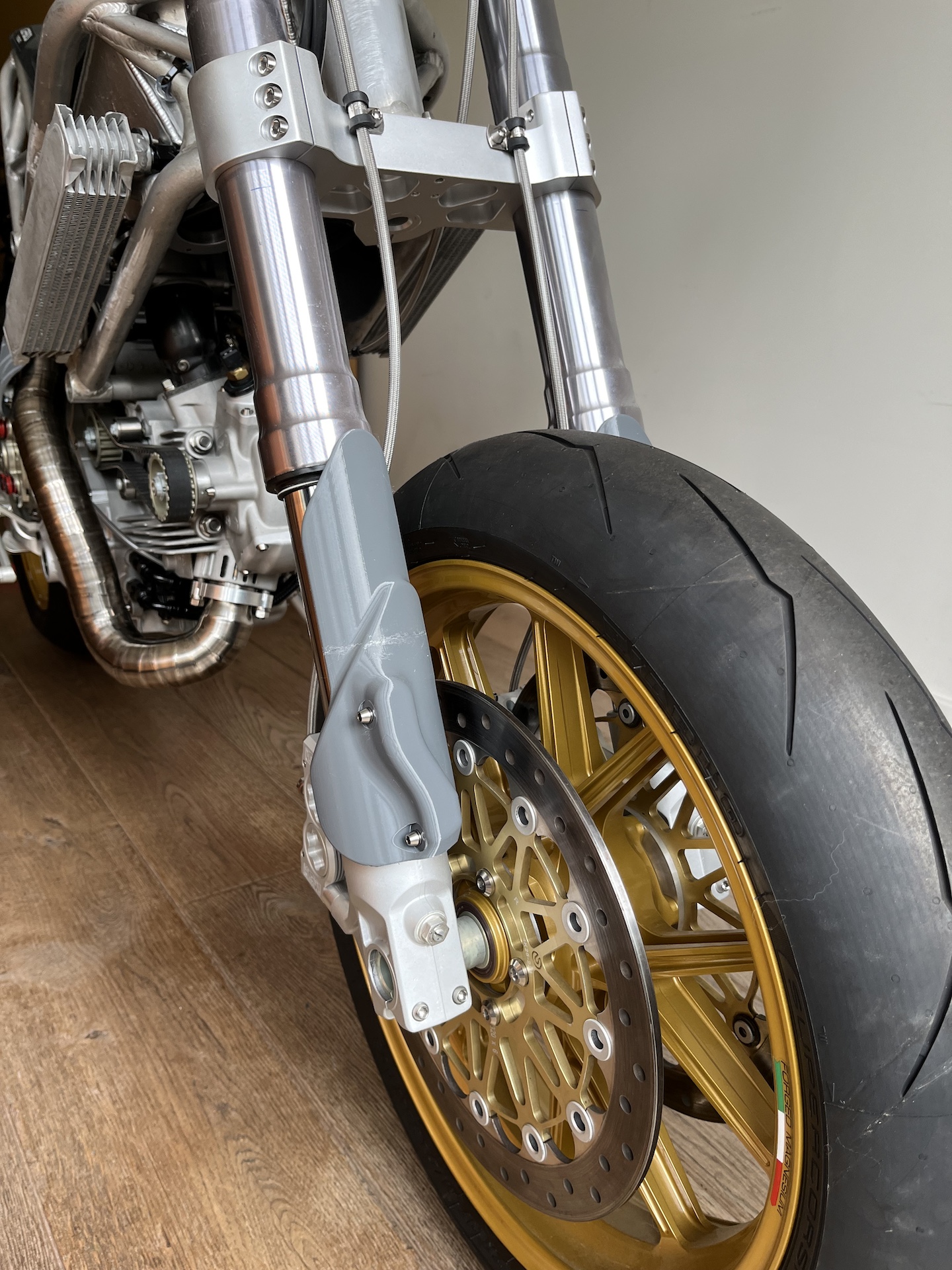
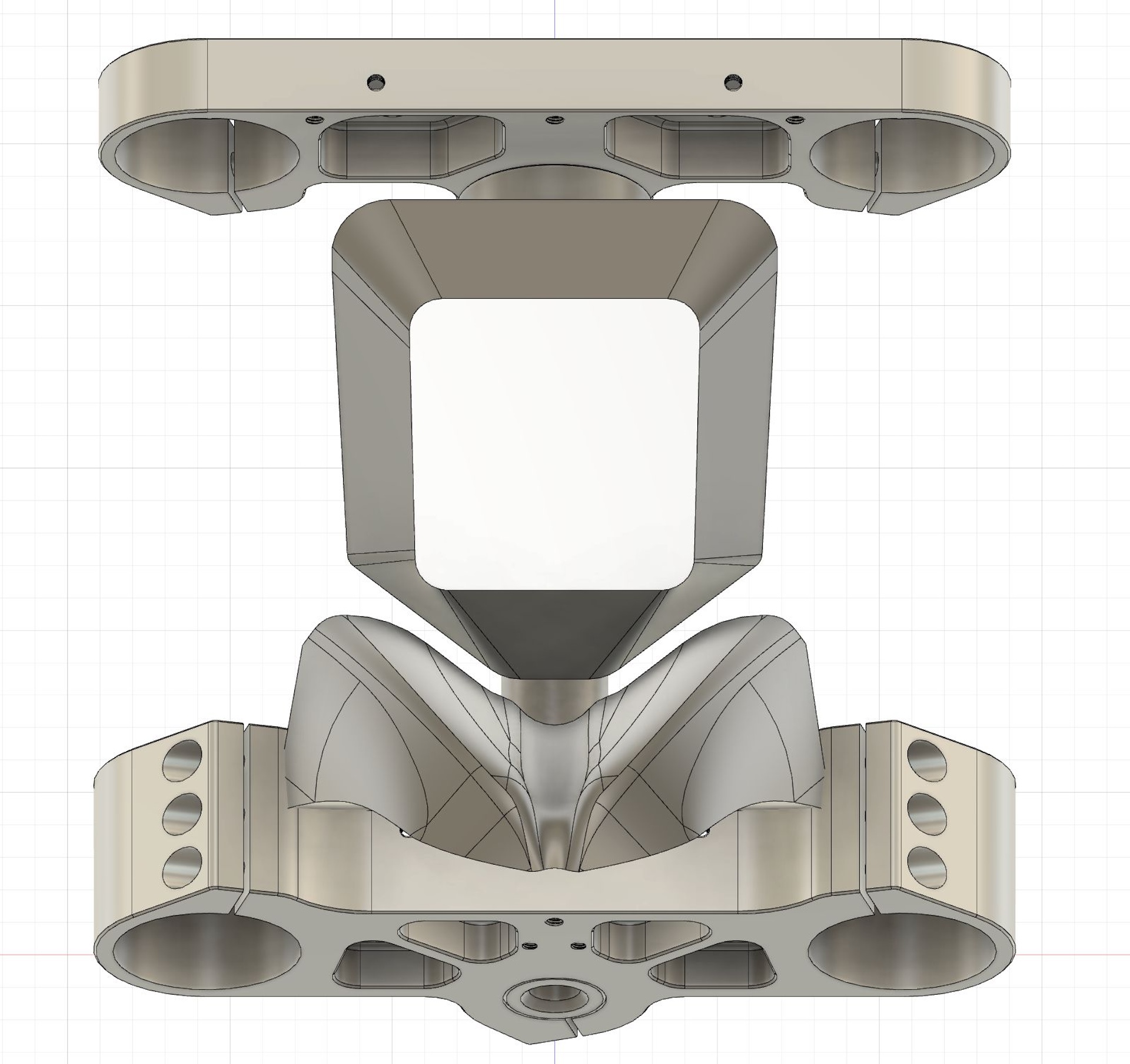
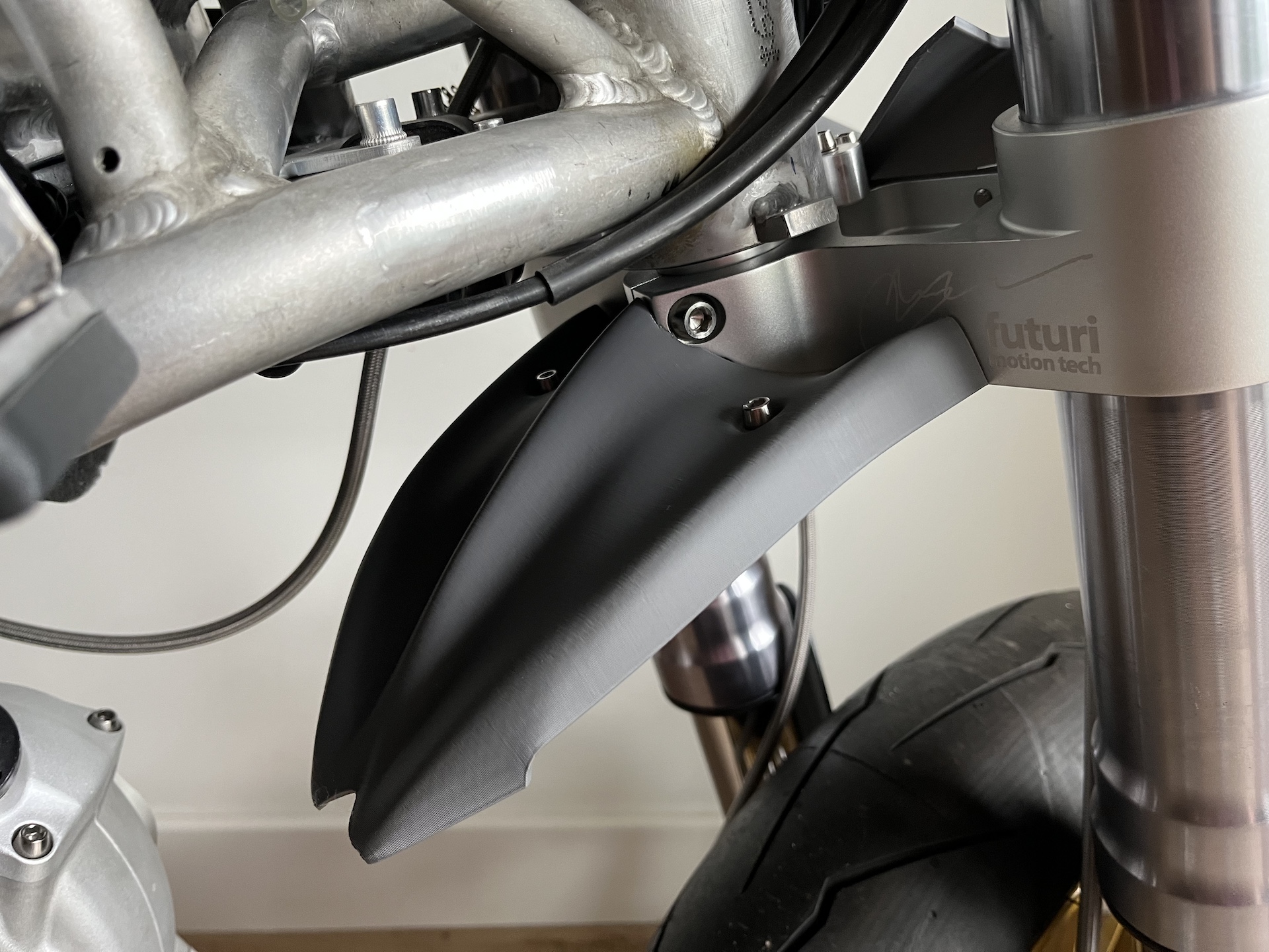
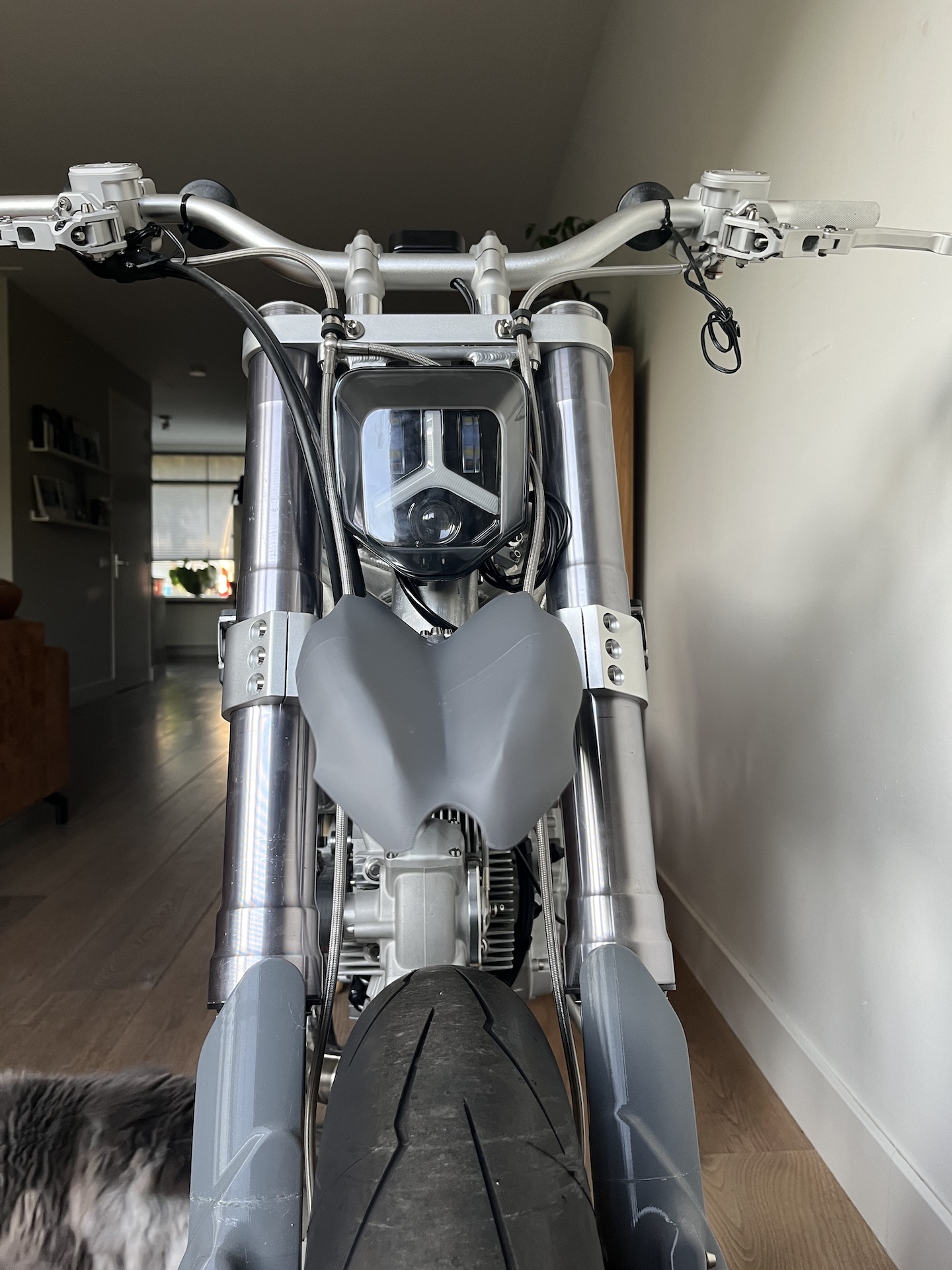
REAR PART OF THE FRONT FENDER
Rear front fender, a 2 part design that perfectly fits around the custom made yokes.
Crazy how much a small part like this can define the looks and lines of the bike… Only took 4 design iterations this time instead of the 8 to 12 for the front part haha.
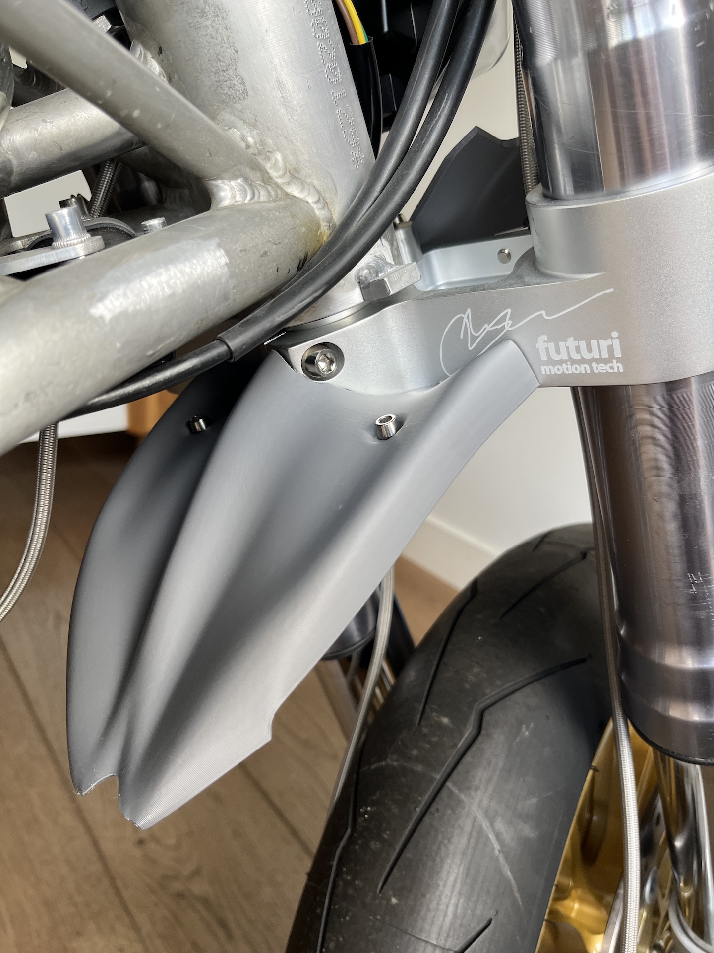
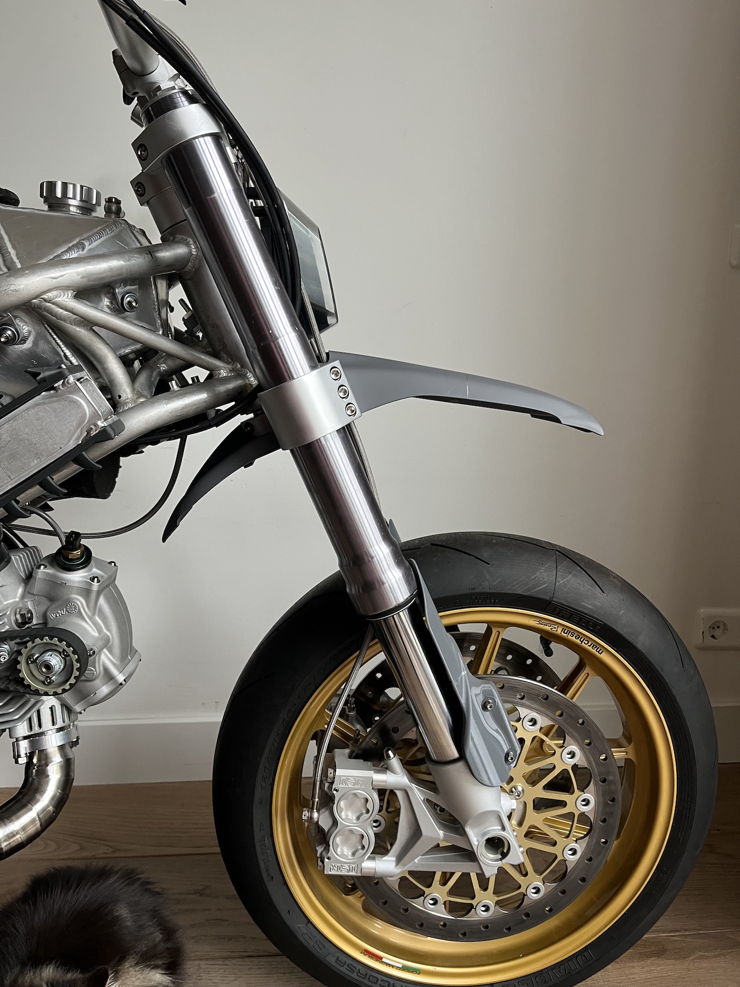
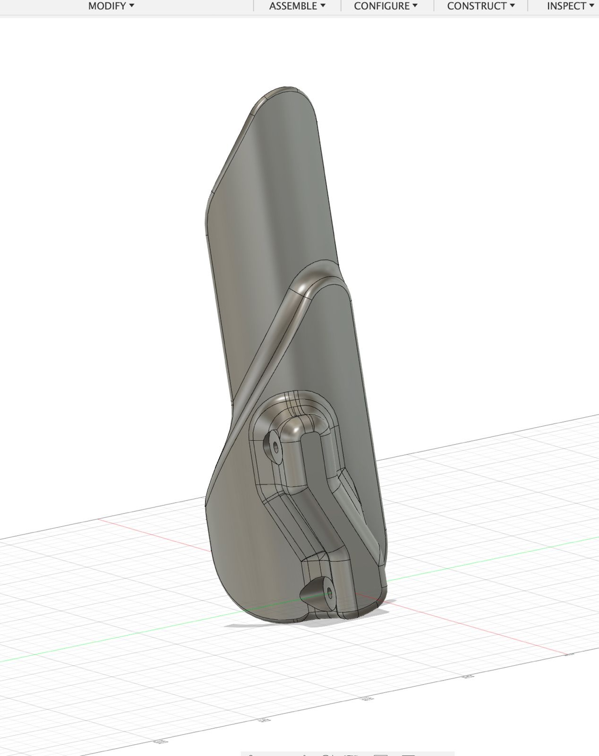
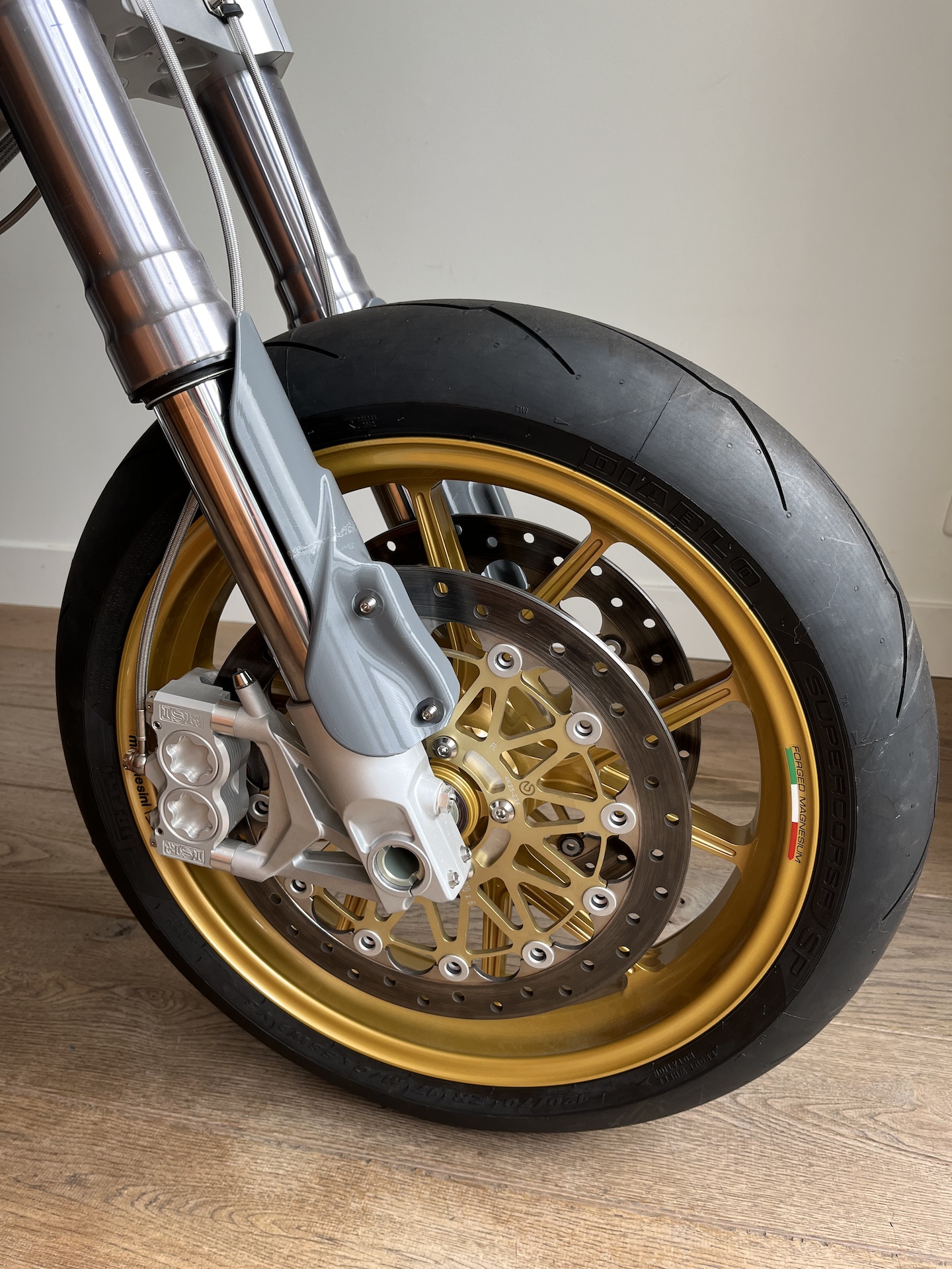
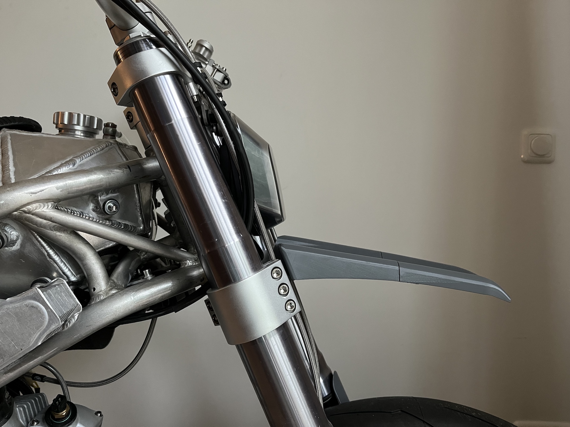
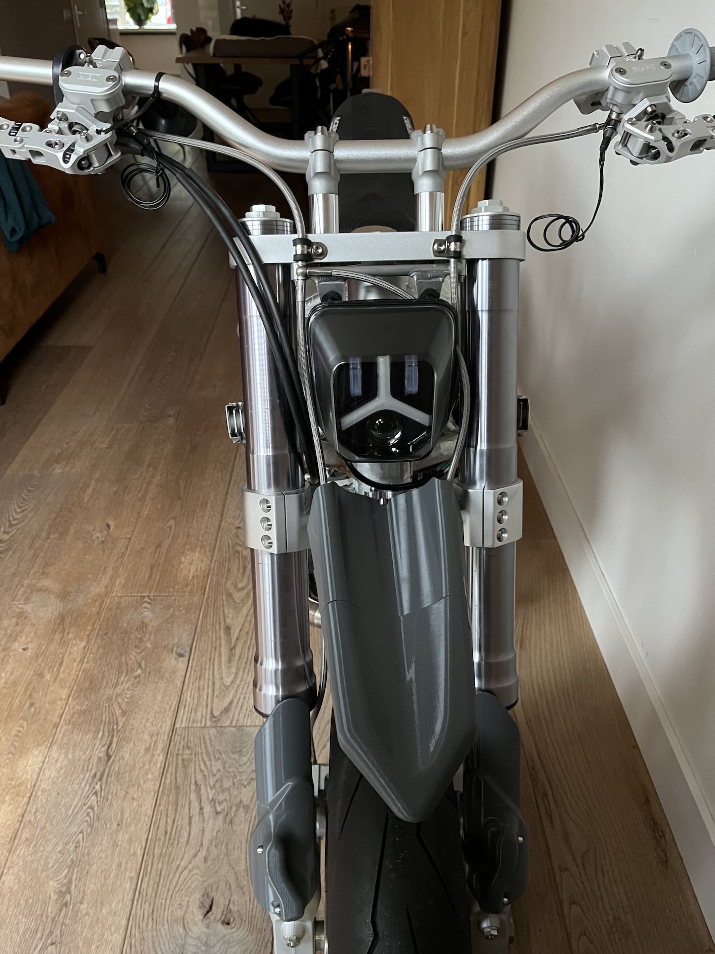
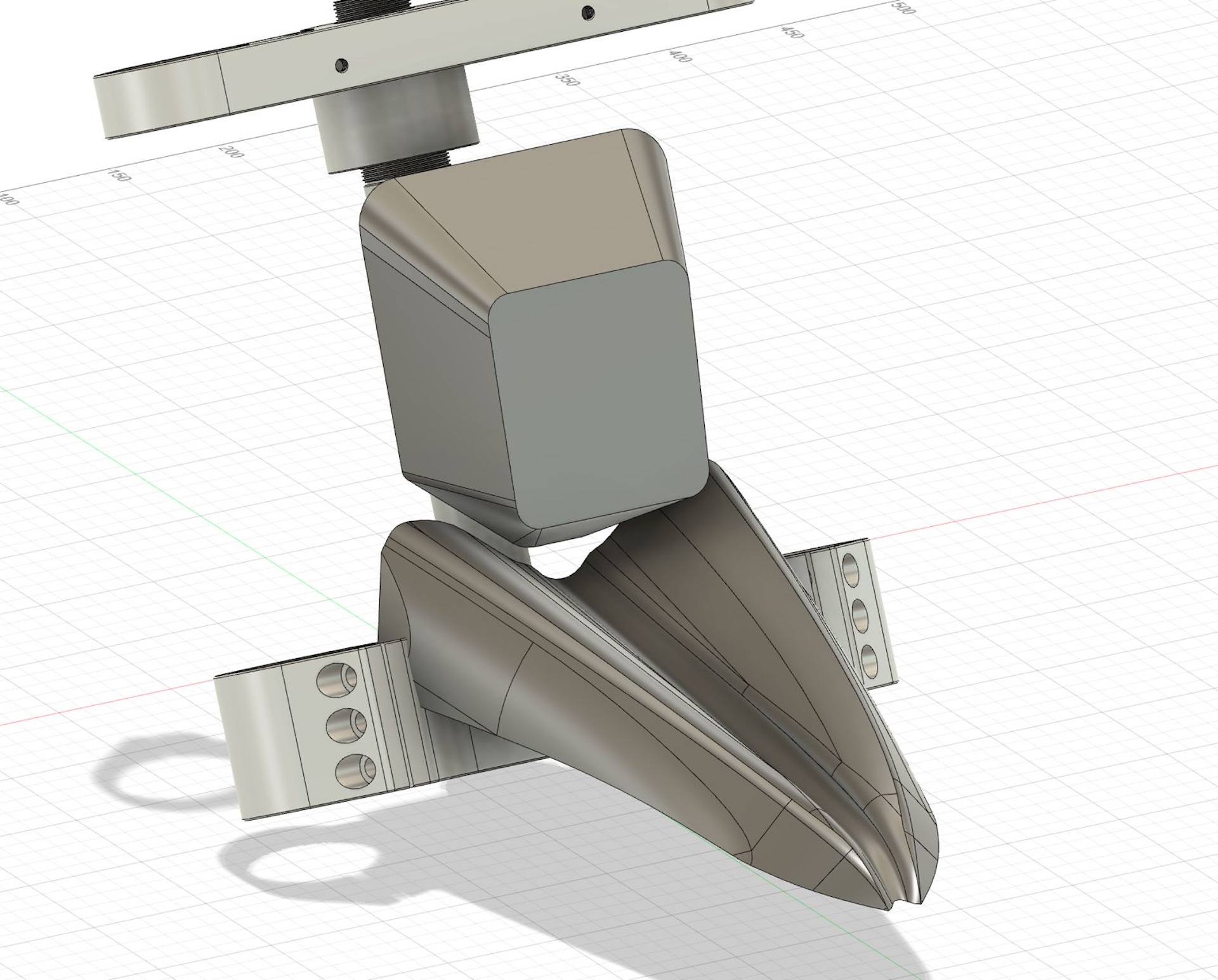
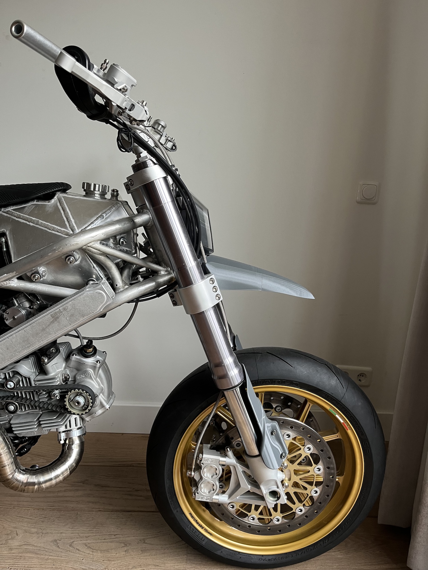
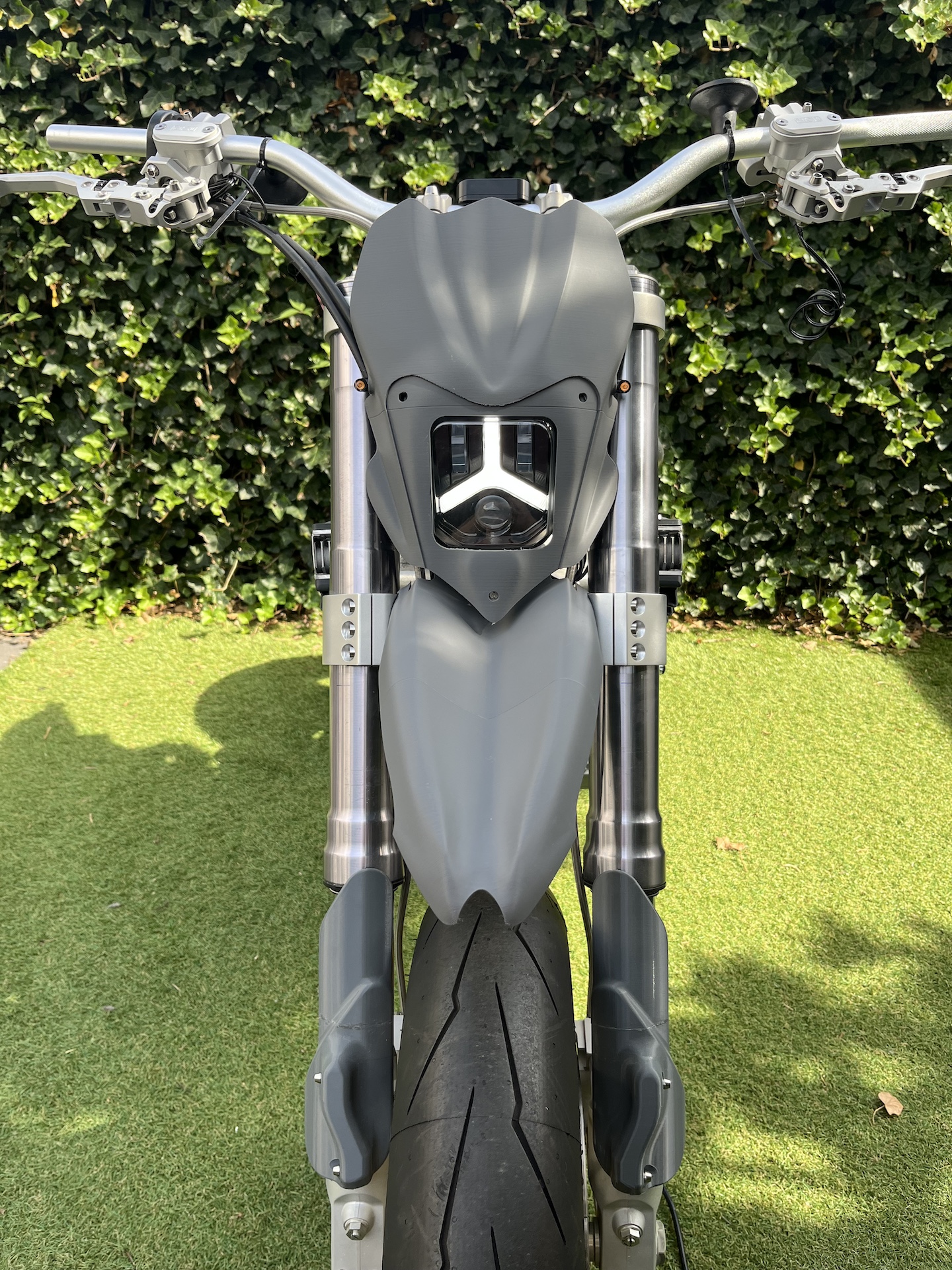
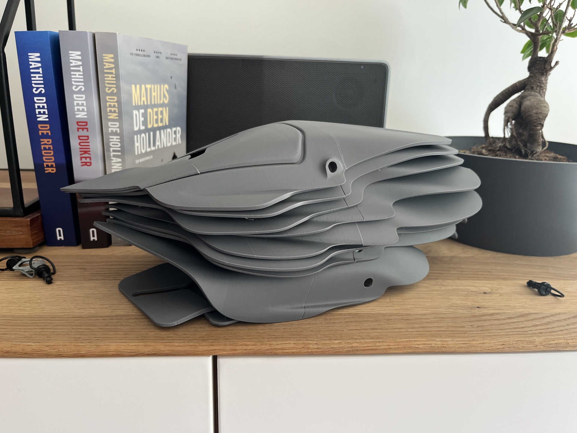
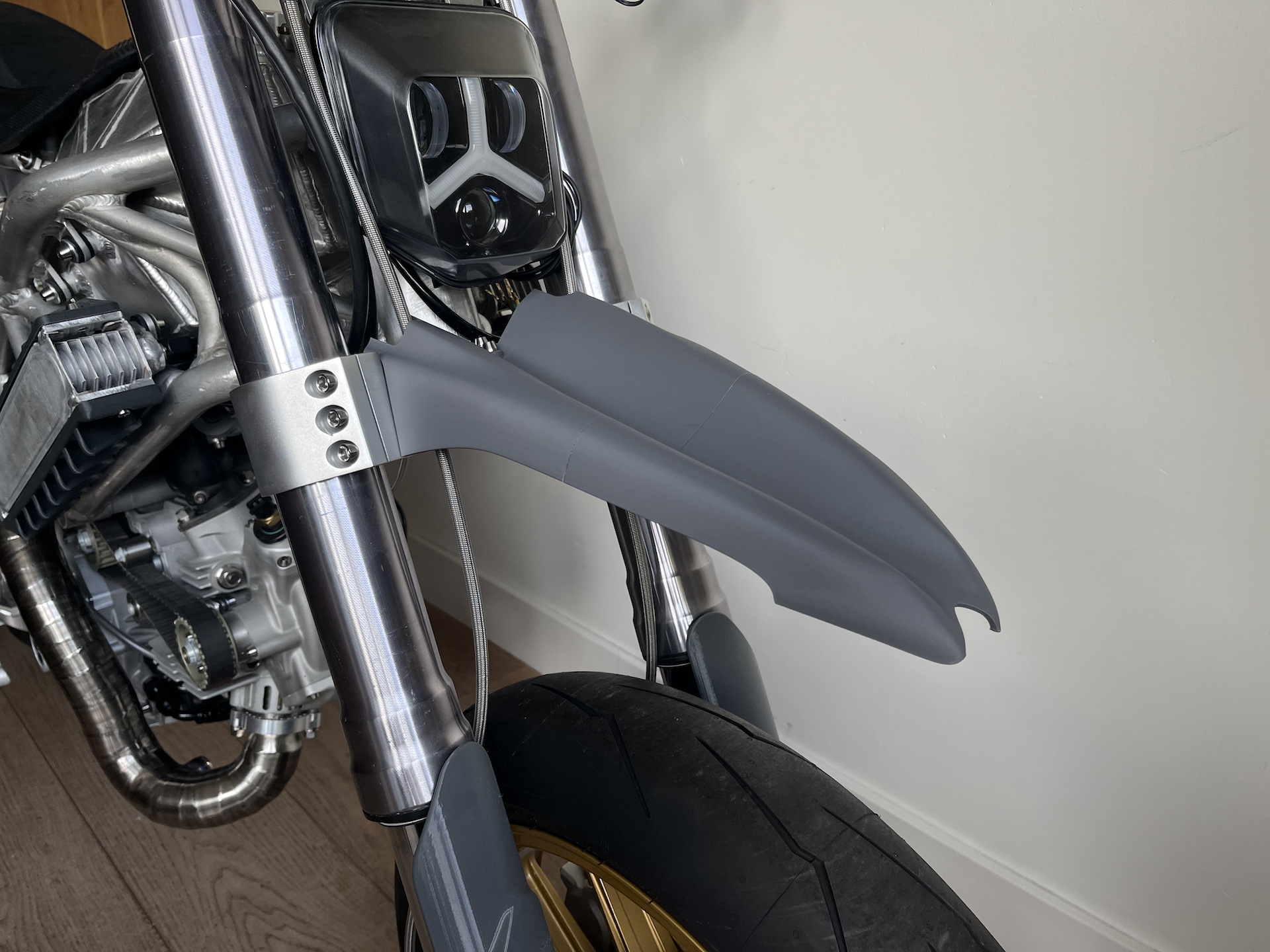
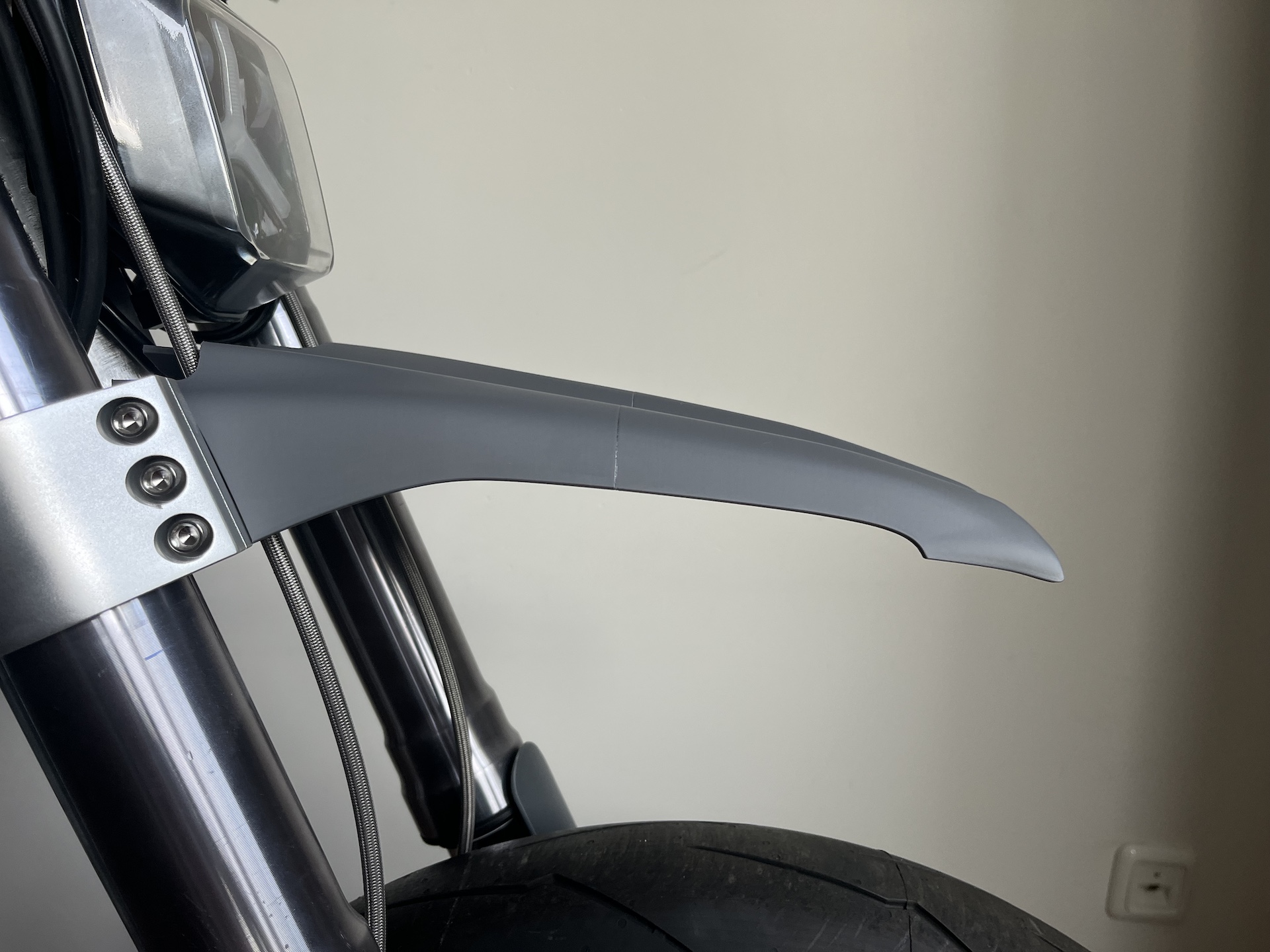
FRONT FENDER
Custom front fender, finally some new progress after almost 8 months of no inspiration on this part… Really happy with this shape and the lines!
The previous 8 versions over the last year just weren’t quite right…
3D printed to validate the looks… Later this year will be printing custom molds to fabricate everything out of carbon fiber.
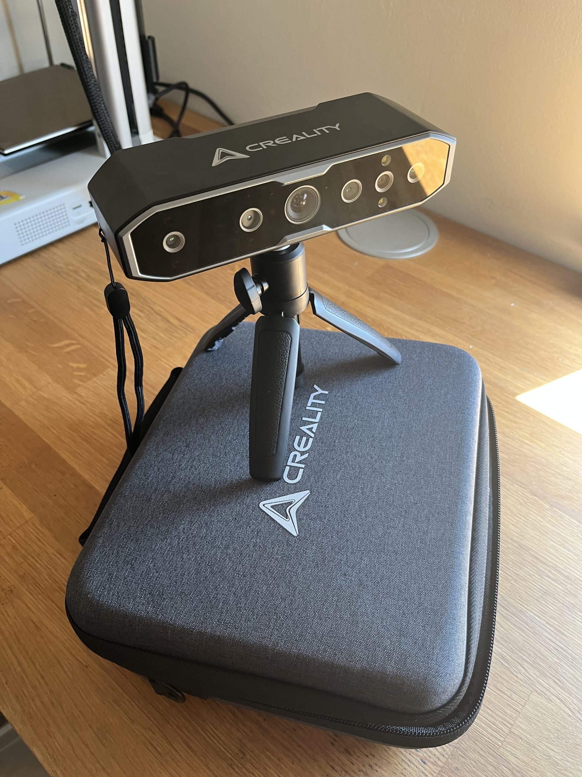
NEW TOOL, 3D SCANNER
New tool in the workshop! 3D scanner from Creality to enable me to design all the carbon fairings perfectly in CAD.
This allows me to model the fairings with a very high accuracy, 3D print the fairings, check the design on the bike and make quick design changes where needed! After all the designs have been finalized I will make molds from the 3D printed parts to fabricate everything out of carbon.
Still learning the whole 3D scanning proces, but getting somewhere.
And of course when the project is done I can hand out 3D printed Desmoto bikes to people
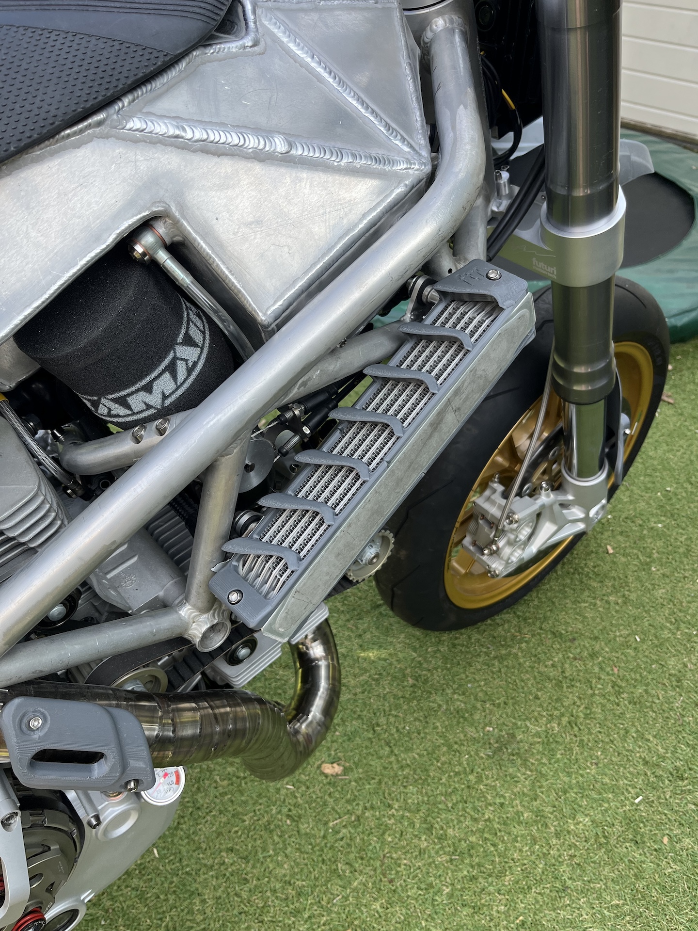
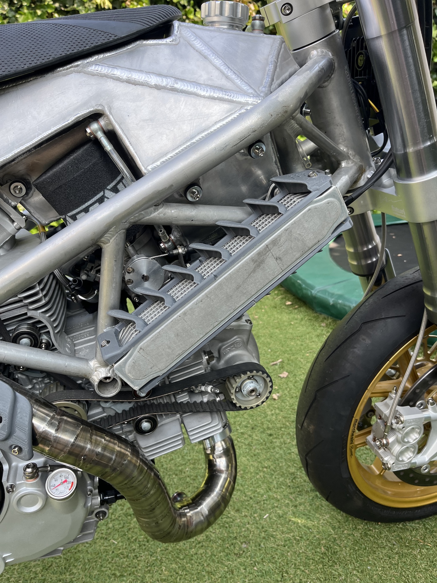
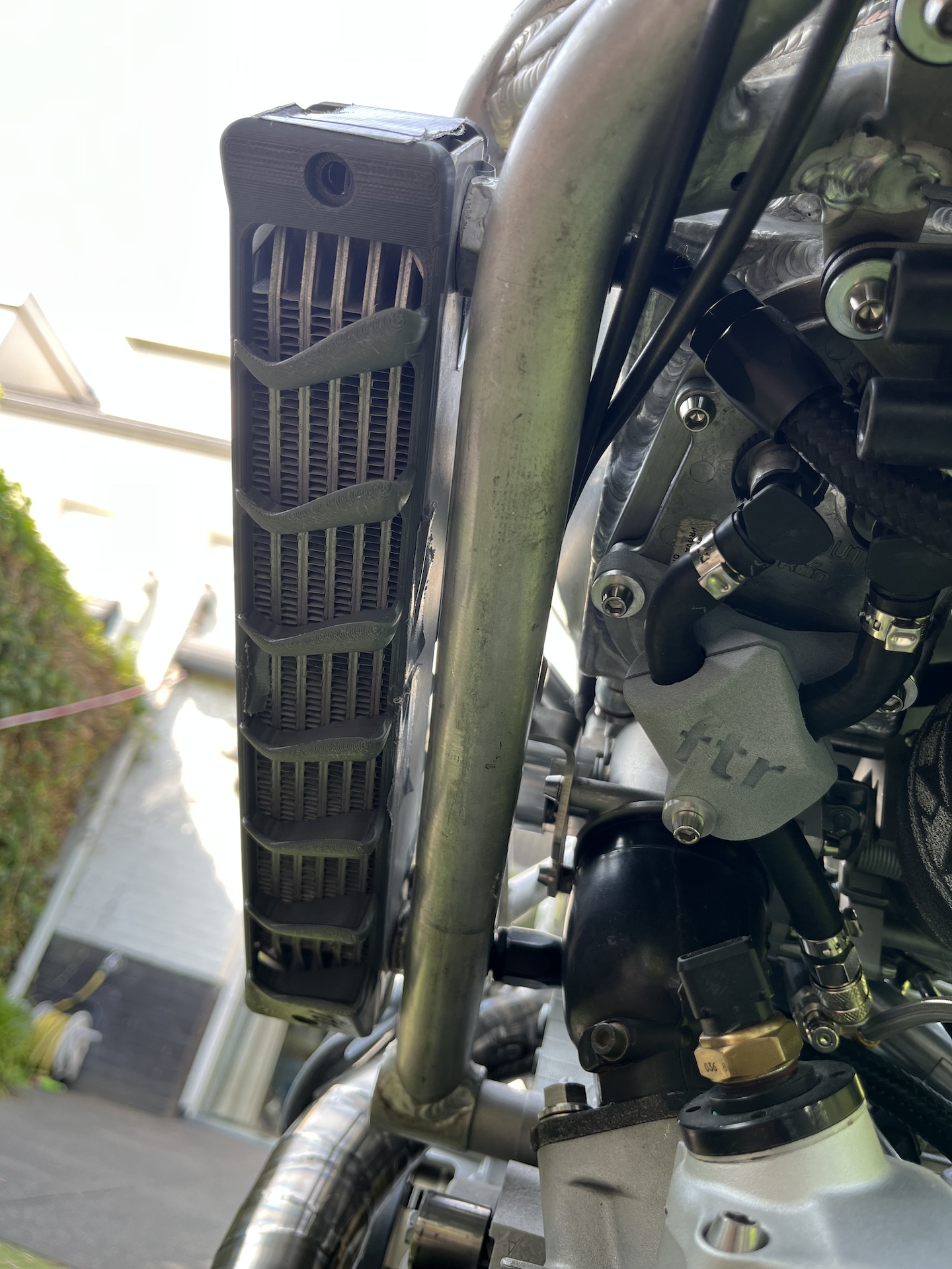
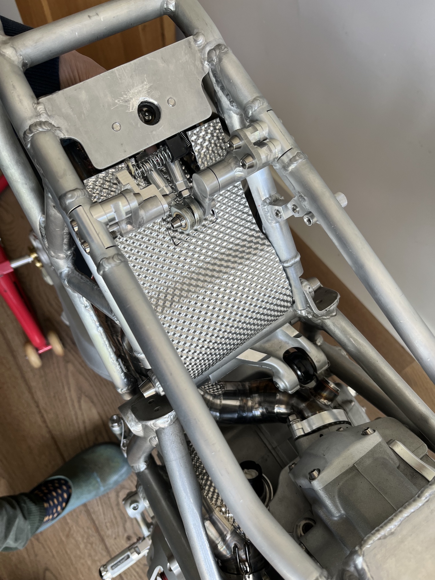
RADIATOR AIR FINS
Radiator air fin design finished! Due to the angle of the 2 oil coolers it is necessary to guide / force some extra air through. These fins do exactly that making sure the oil temperature stays manageable! But with an extra bonus, they look really nice haha.
Currently 3D printed out of PETG to mock-up, later they will be printed out of Nylon PA6 + Carbon fiber to make sure they can handle the heat from the oil coolers.
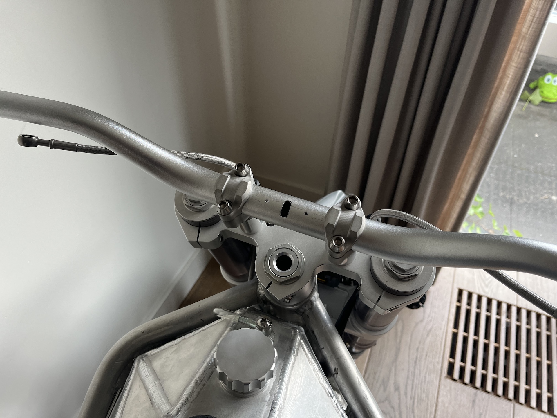
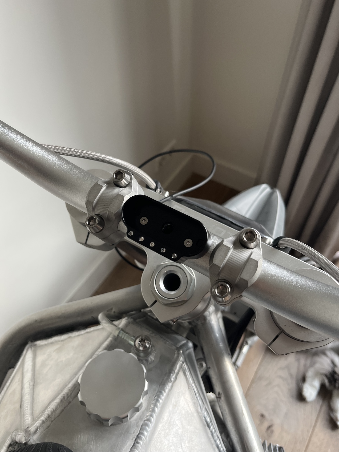
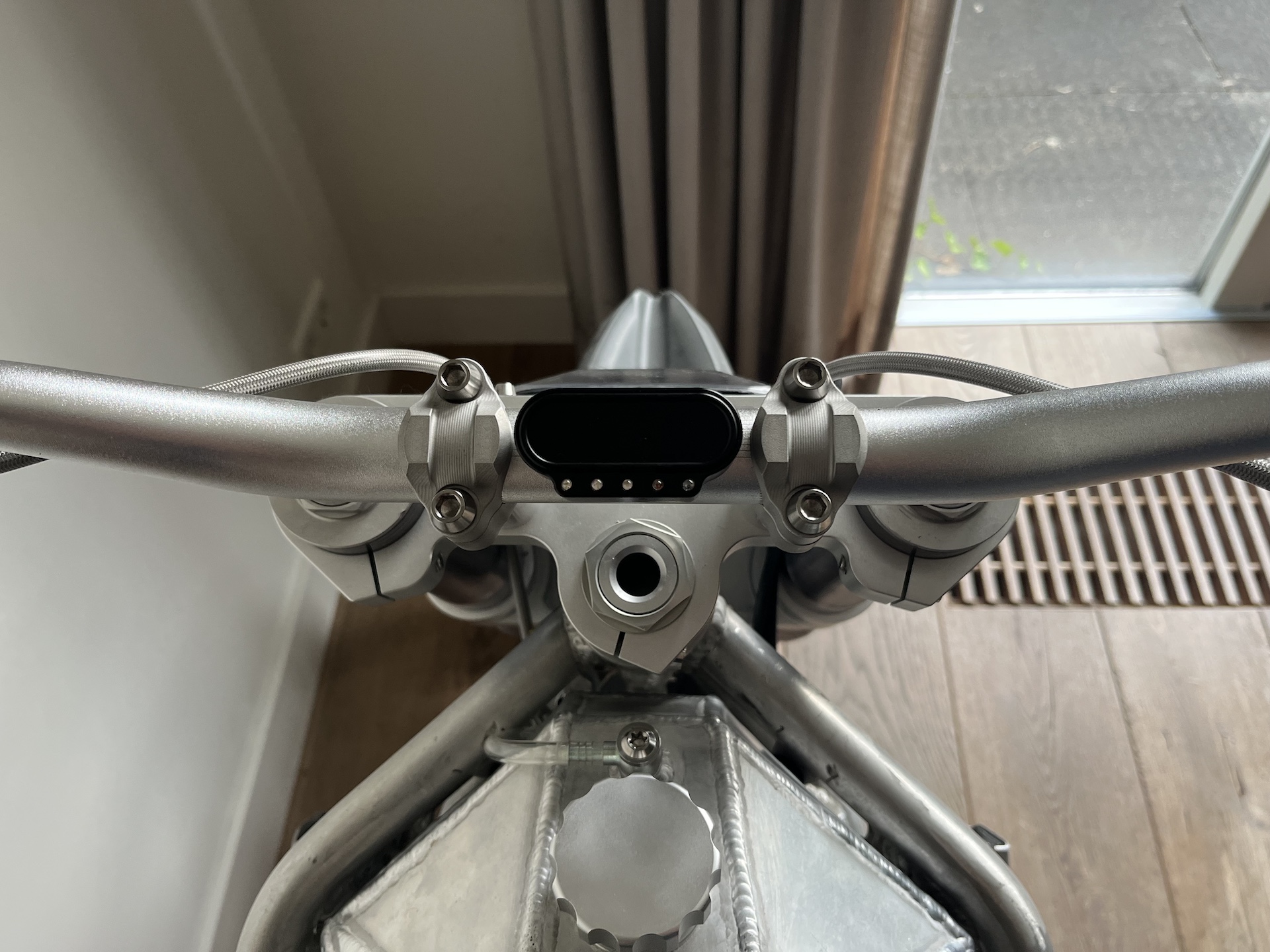
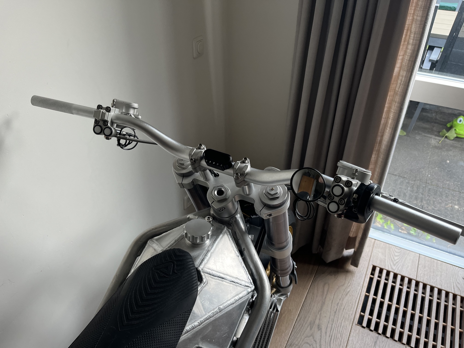
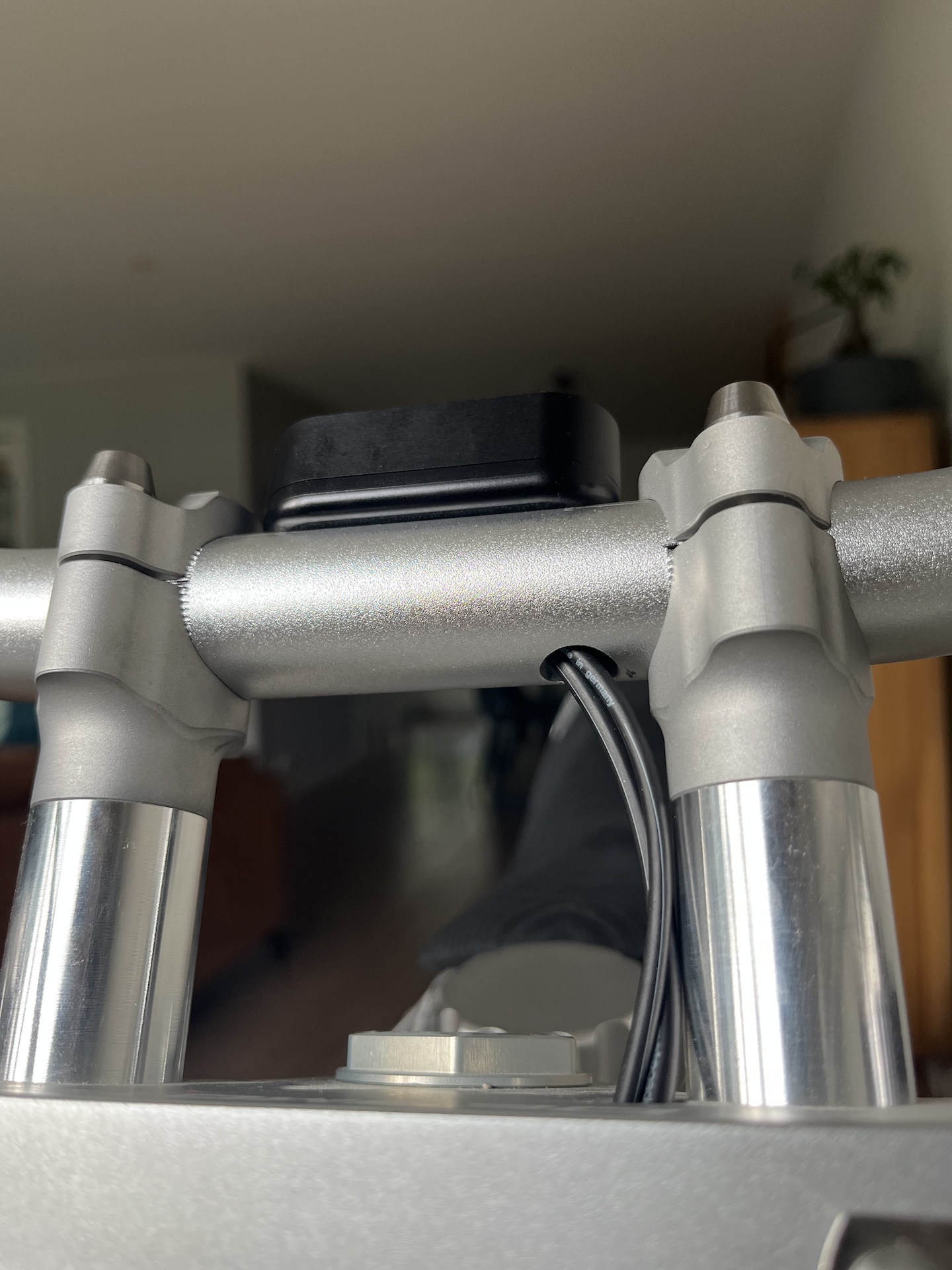
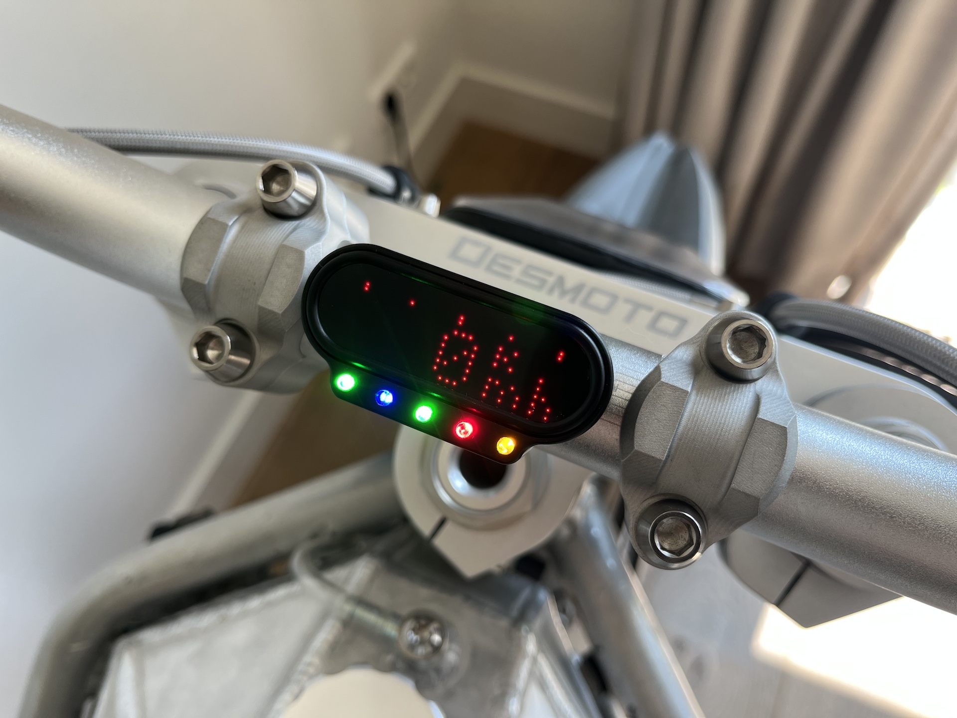
MOTOGADGET MOTOSCOPE MINI
Motoscope Mini integrated on the handlebars. Super slick and clean. Wires will all be routed through the bars making sure not a single wire will be in sight.
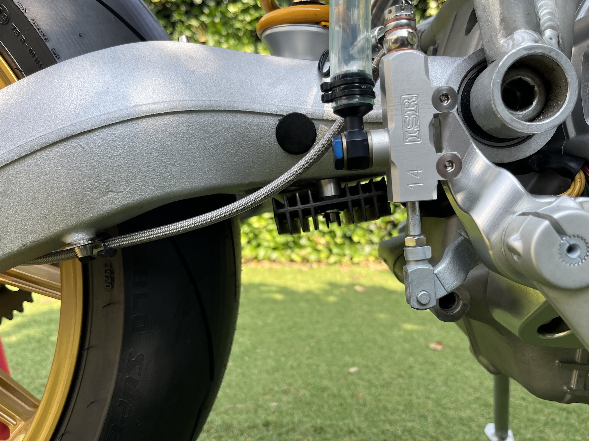
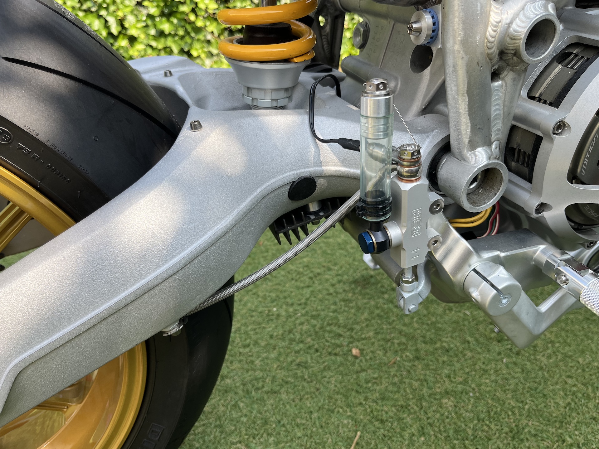
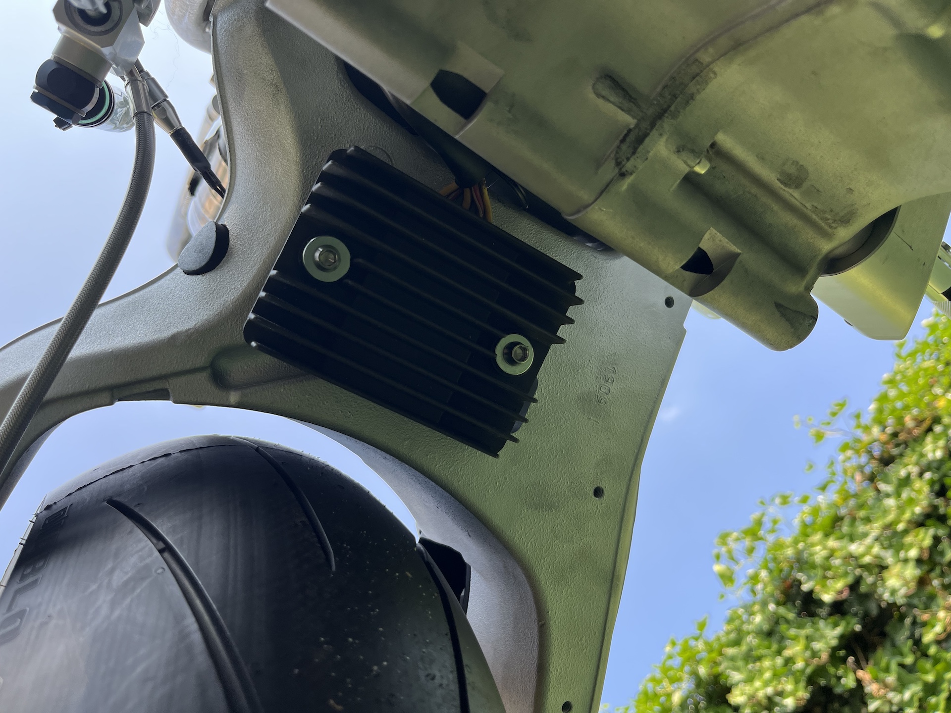
MOUNTING THE RECTIFIER
I installed the rectifier beneath the swingarm. Probably a questionable location, but I think it will work just fine. It’s modified to allow mounting using rubber grommets to reduce vibrations, and in this location it will at least get enough cooling. Water and dirt won’t be an easy, since on my Hypermotard the rectifier is mounted in the direct spray line of the front wheel.
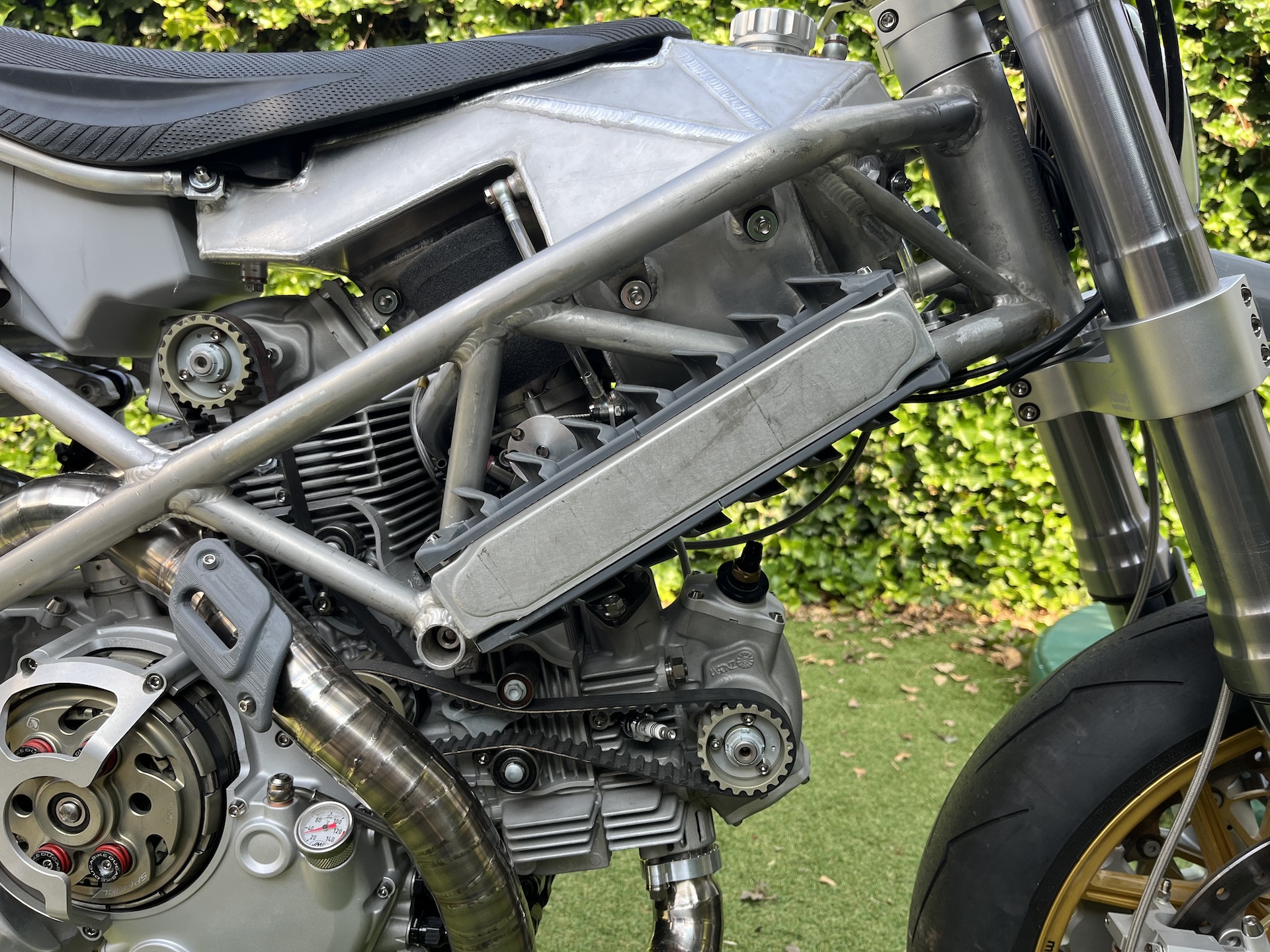
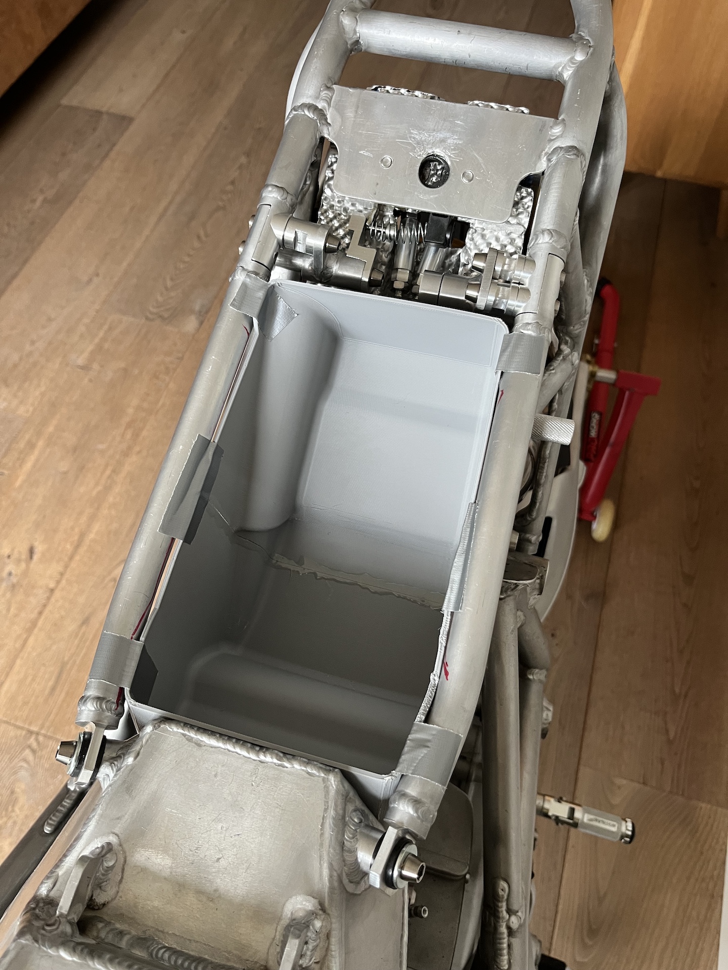
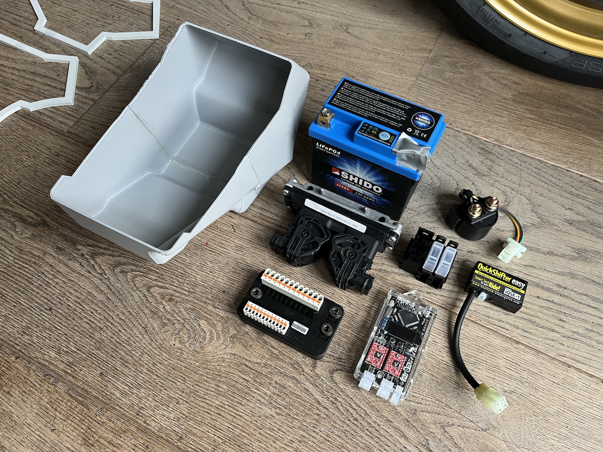
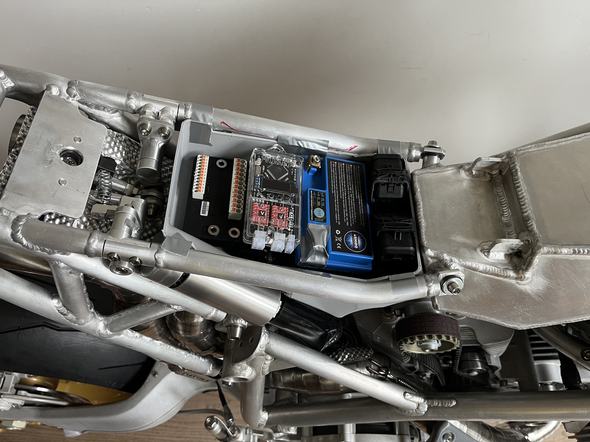
ELECTRONICS TRAY
Electronics tray design is done! 3D printed and the design will later be used to make molds of to fabricate everything out of carbon fiber.
Took some tries to get the shape exactly how I wanted it to be, but really happy how it follows the lines of the vertical cylinder for example.
It was an extremely tight fit to get all the electronics in there, so I am going to need to be creative with fabricating the wiring loom to make sure that also fits.
Also the custom crankcase breather now has a place.
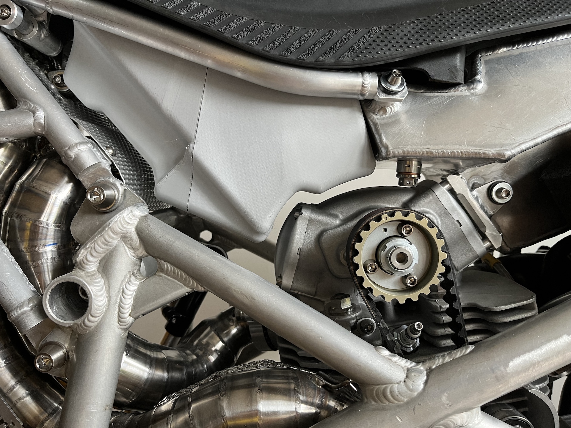
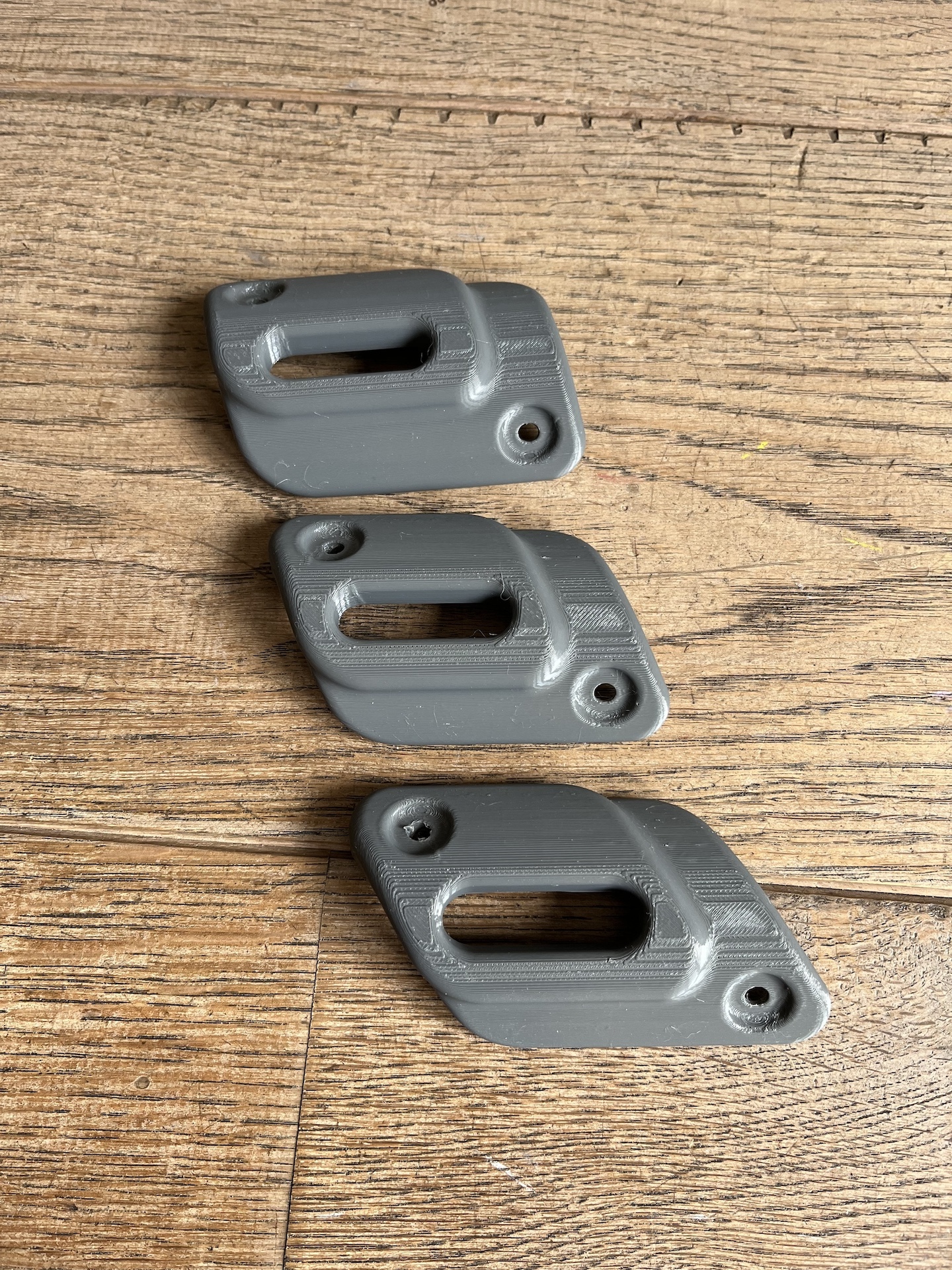
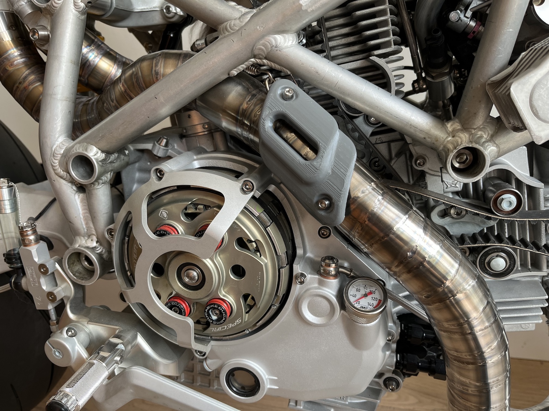
UNDER SEAT HEAT SHIELD
It seems everybody is worried about heat on this project… No worries, another custom heat shield made out of 0.5mm aluminium to protect the seat and electronics tray.
Thinnest aluminium I have ever welded… Took me some time to get the settings correct before I was able to weld aluminium this thin!
Do the welds look great? No not amazing, however they are solid! But on material this thin getting welds that look amazing is secondary. I am glad I didn’t blast through. Hats off to anybody that is able to weld aluminium this thin and also make it look super nice!
For the people interested in the weld settings:
250hz AC
32% balance
40A ignition
35A peak
10A base
Pulse 75hz @ 75%
Welded with a pedal
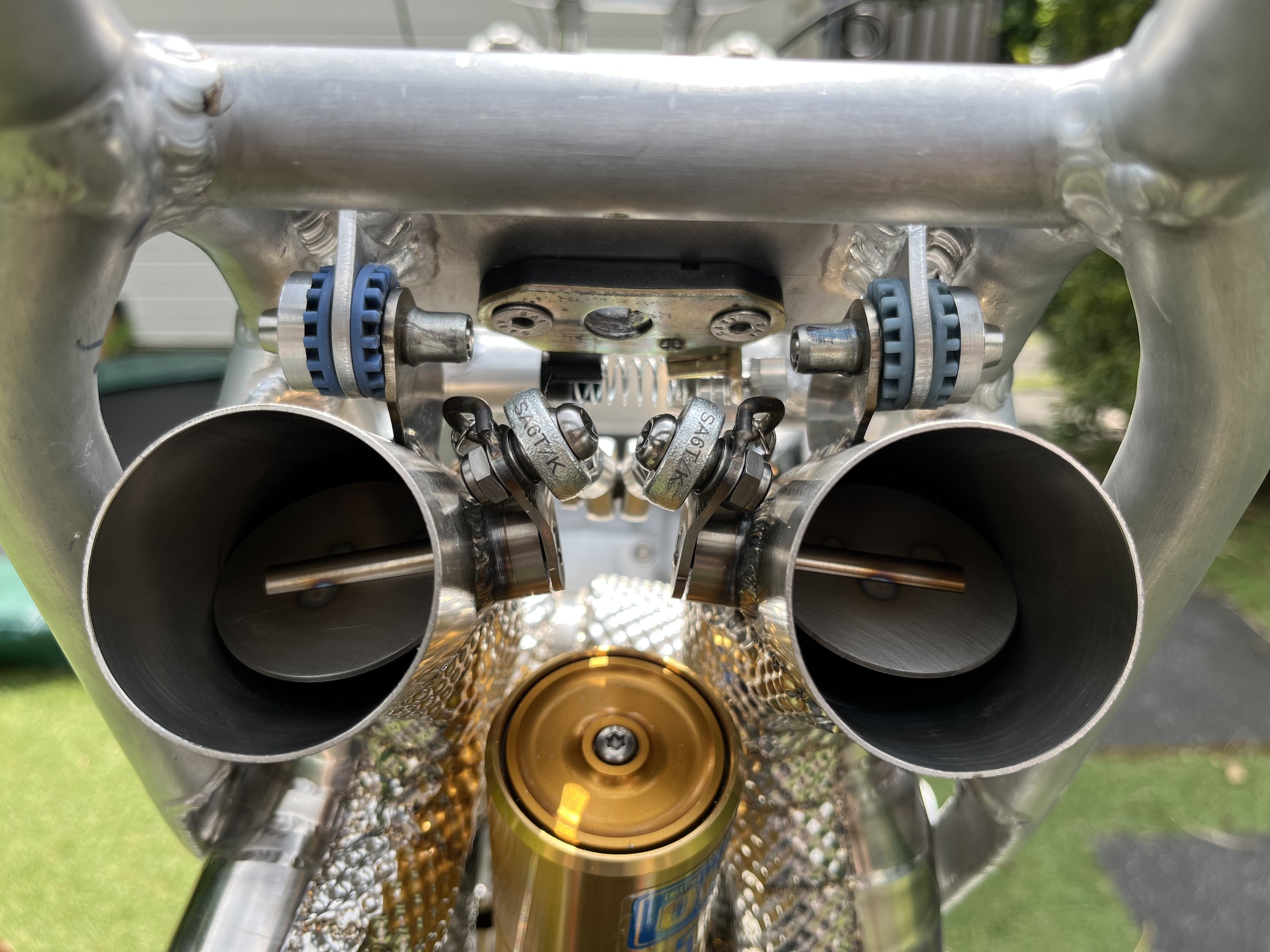
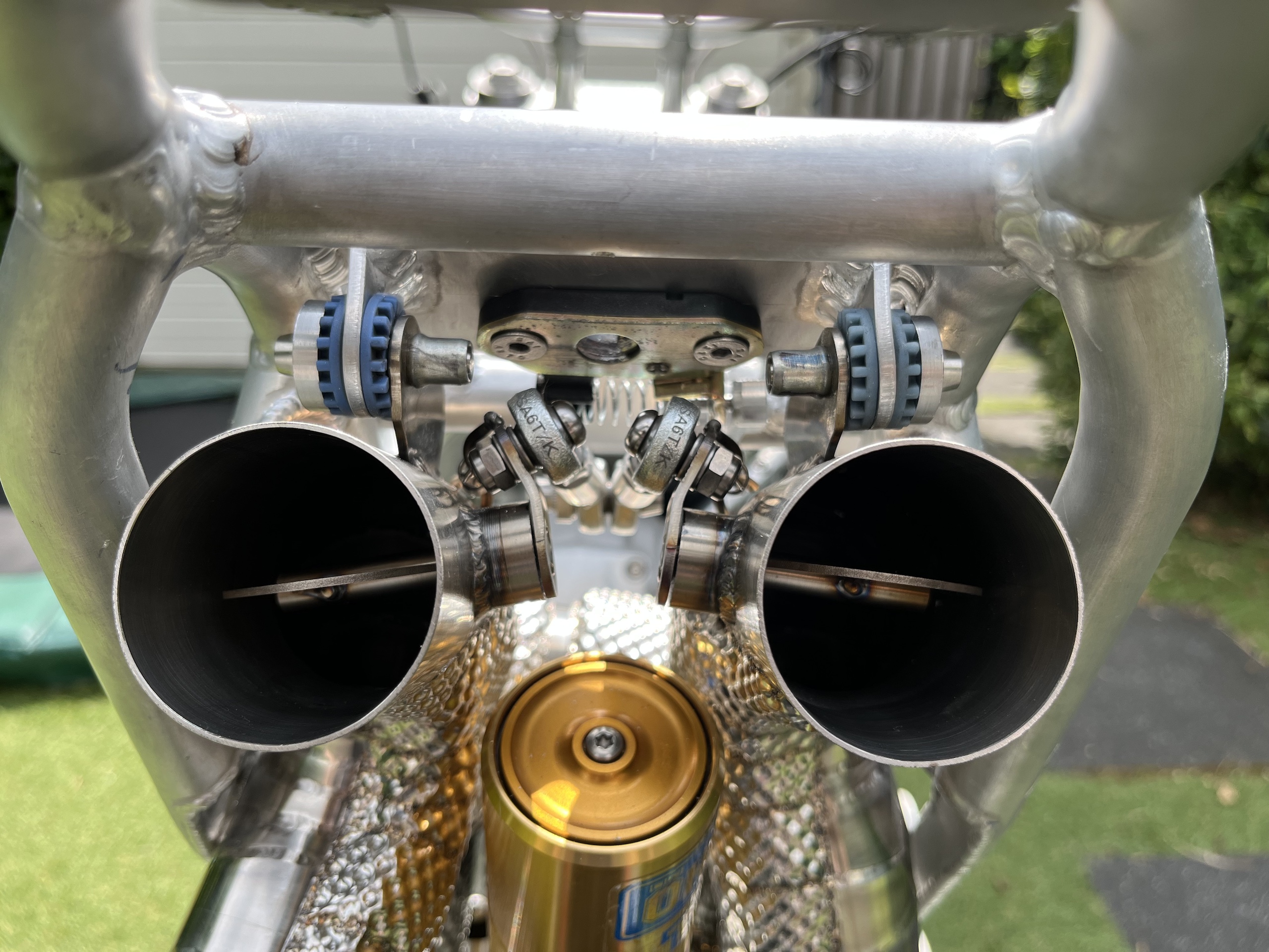
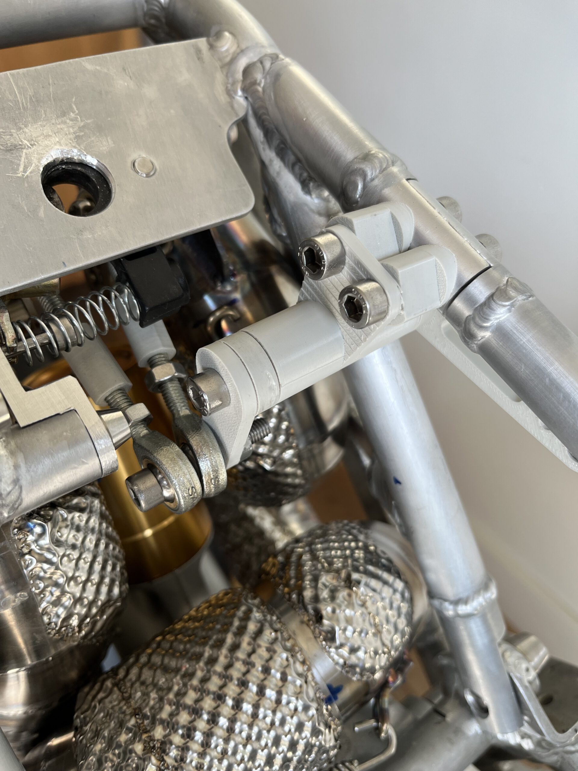
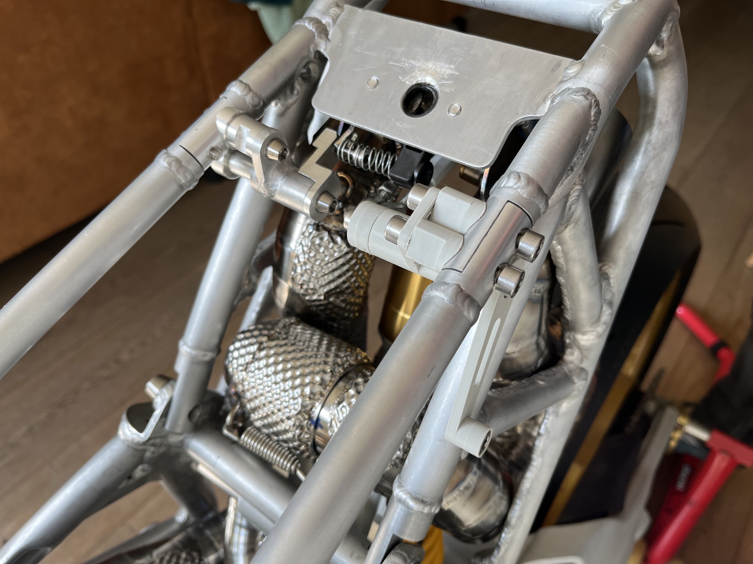
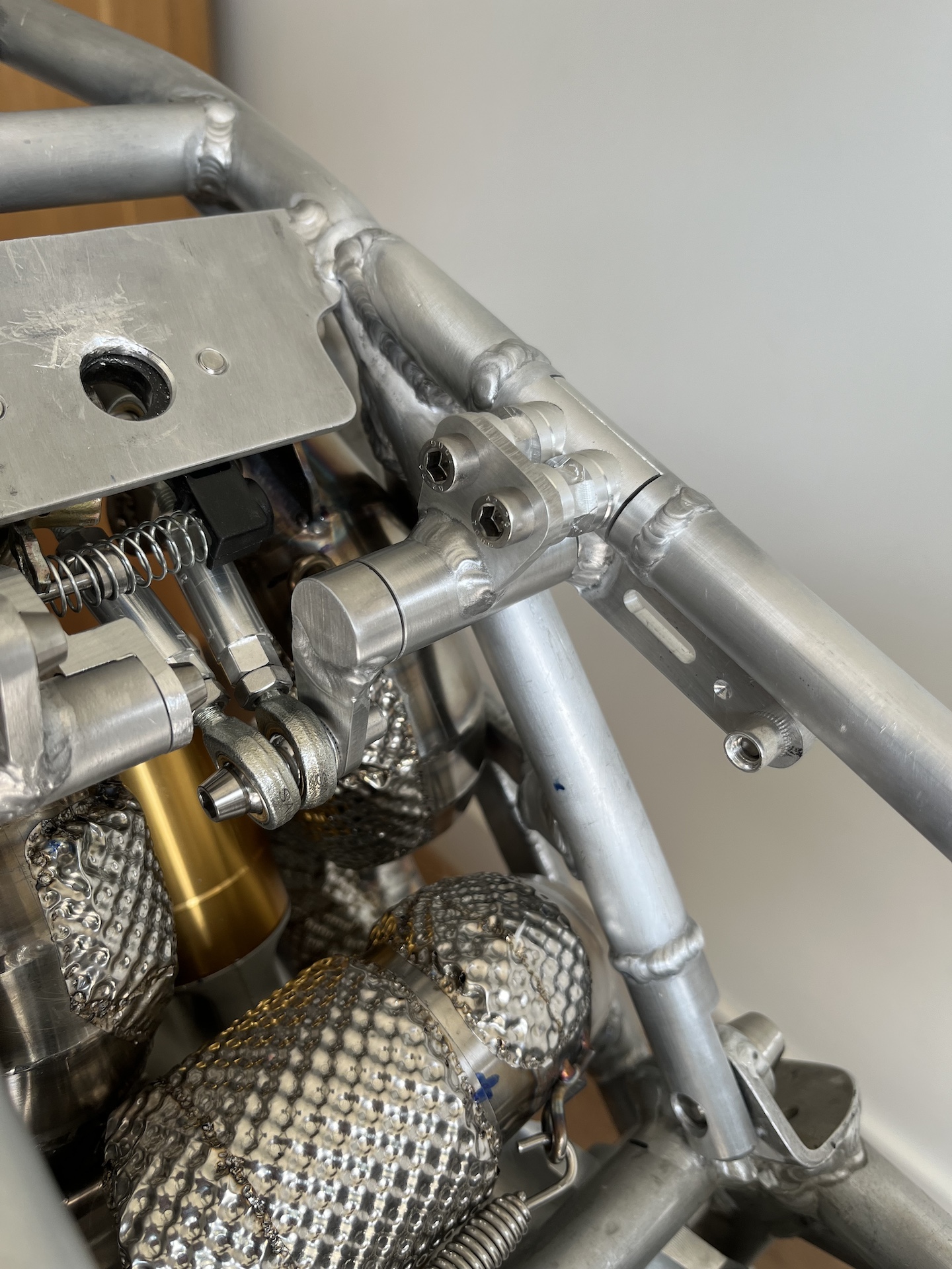
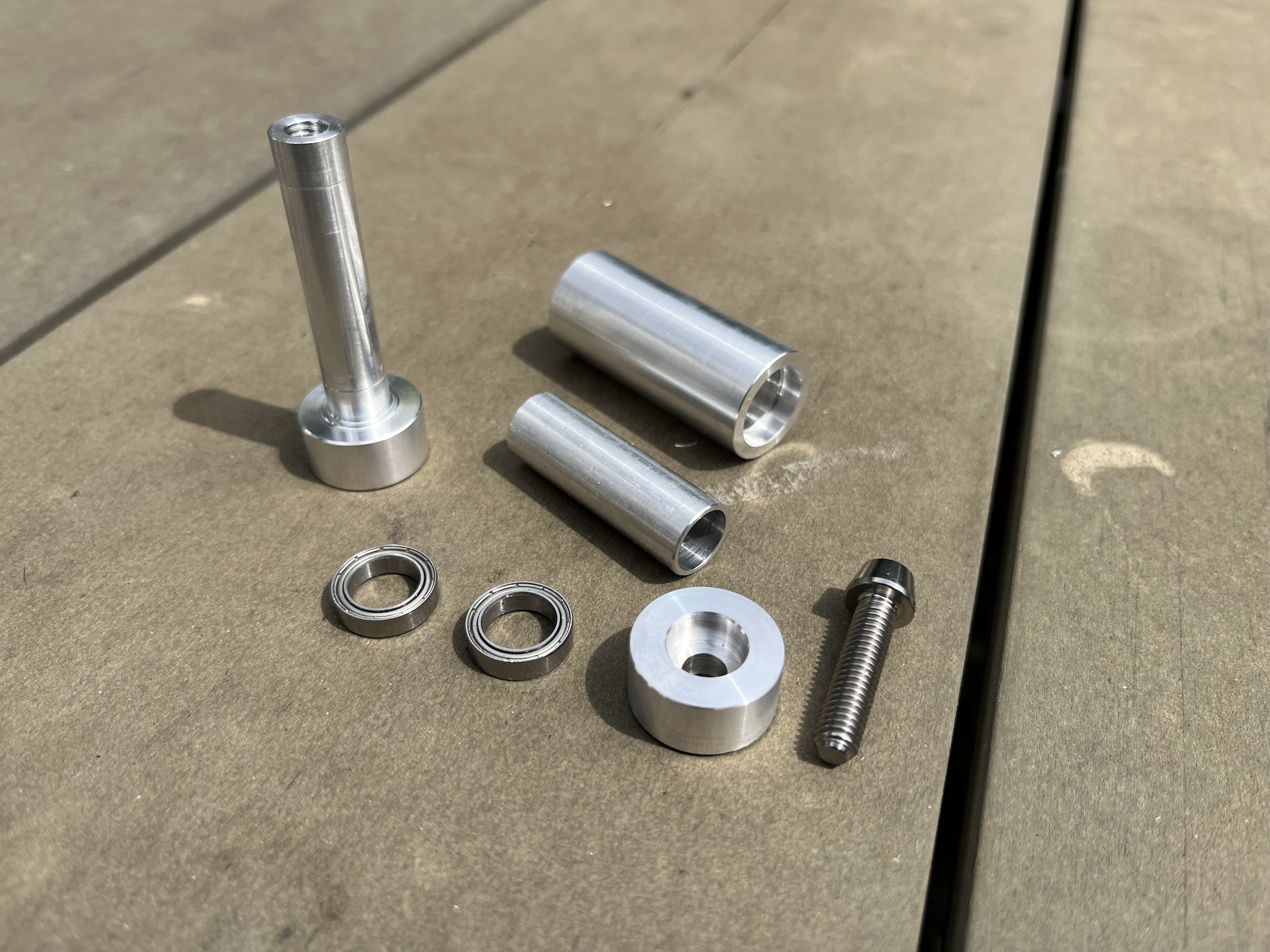
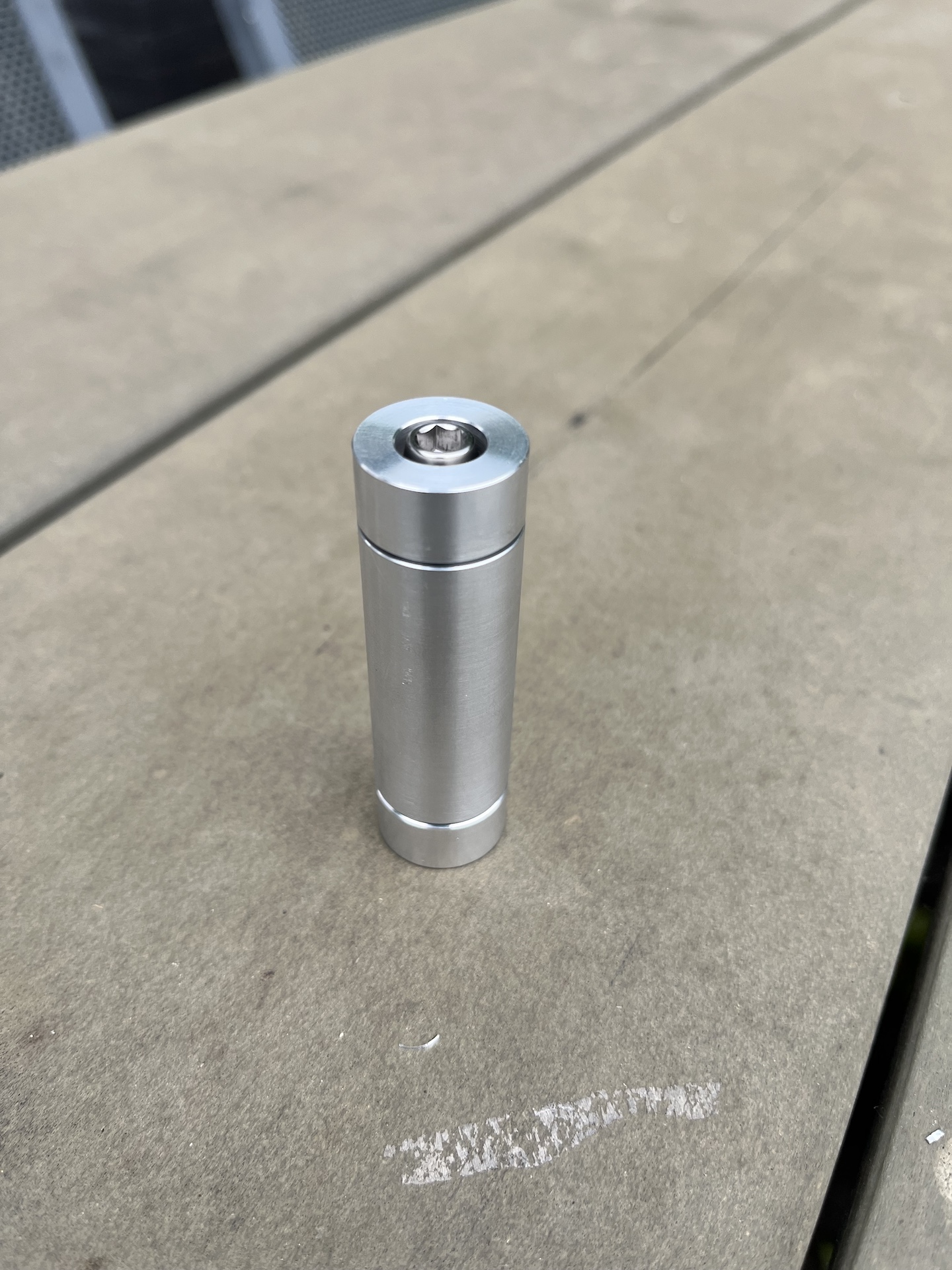
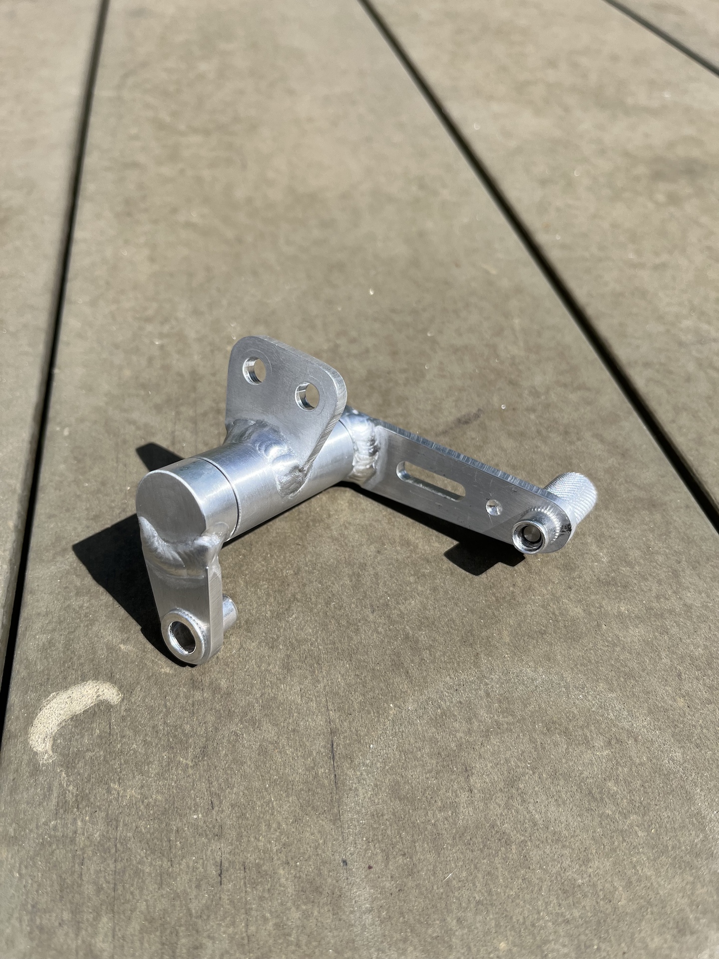
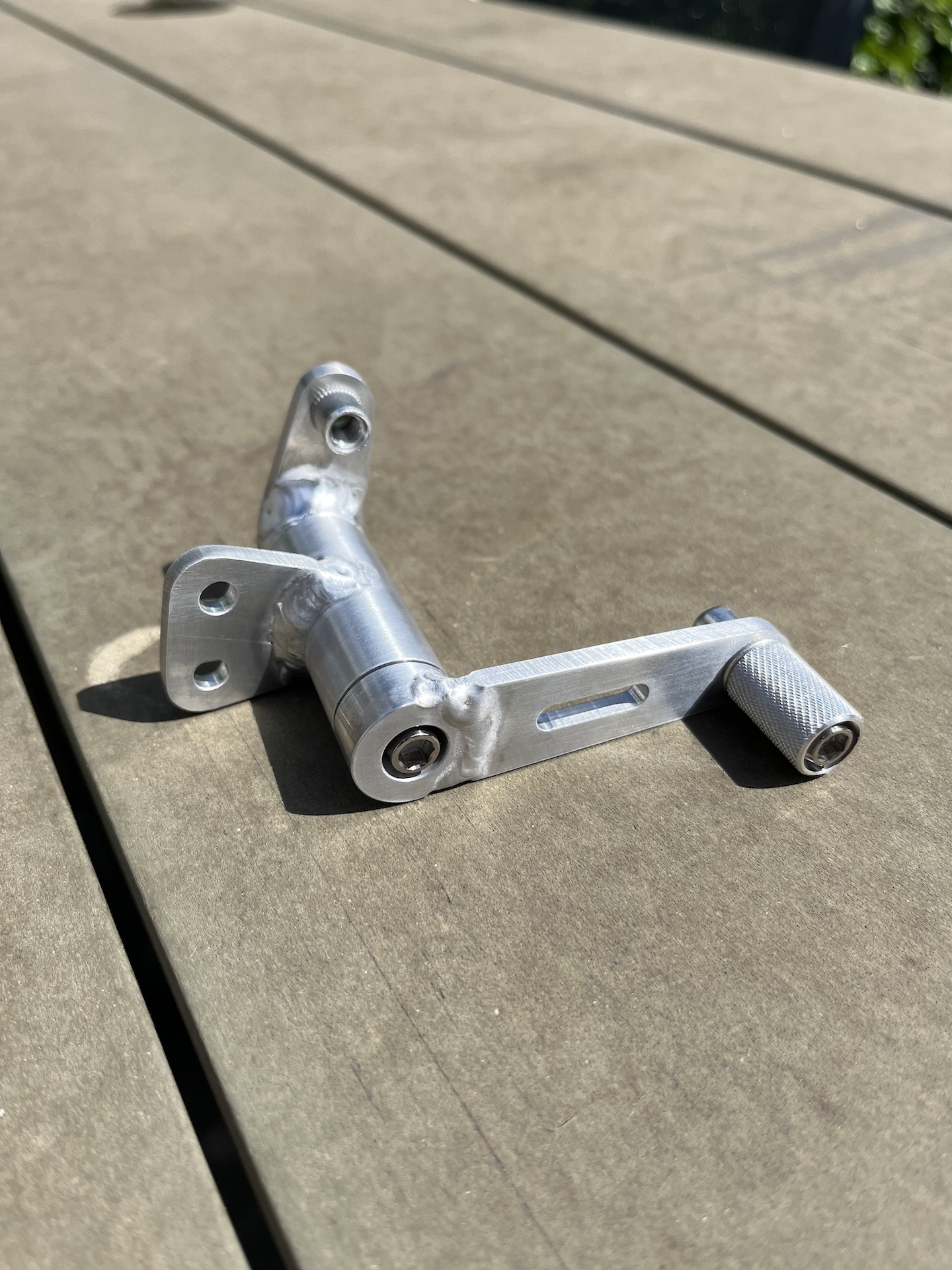
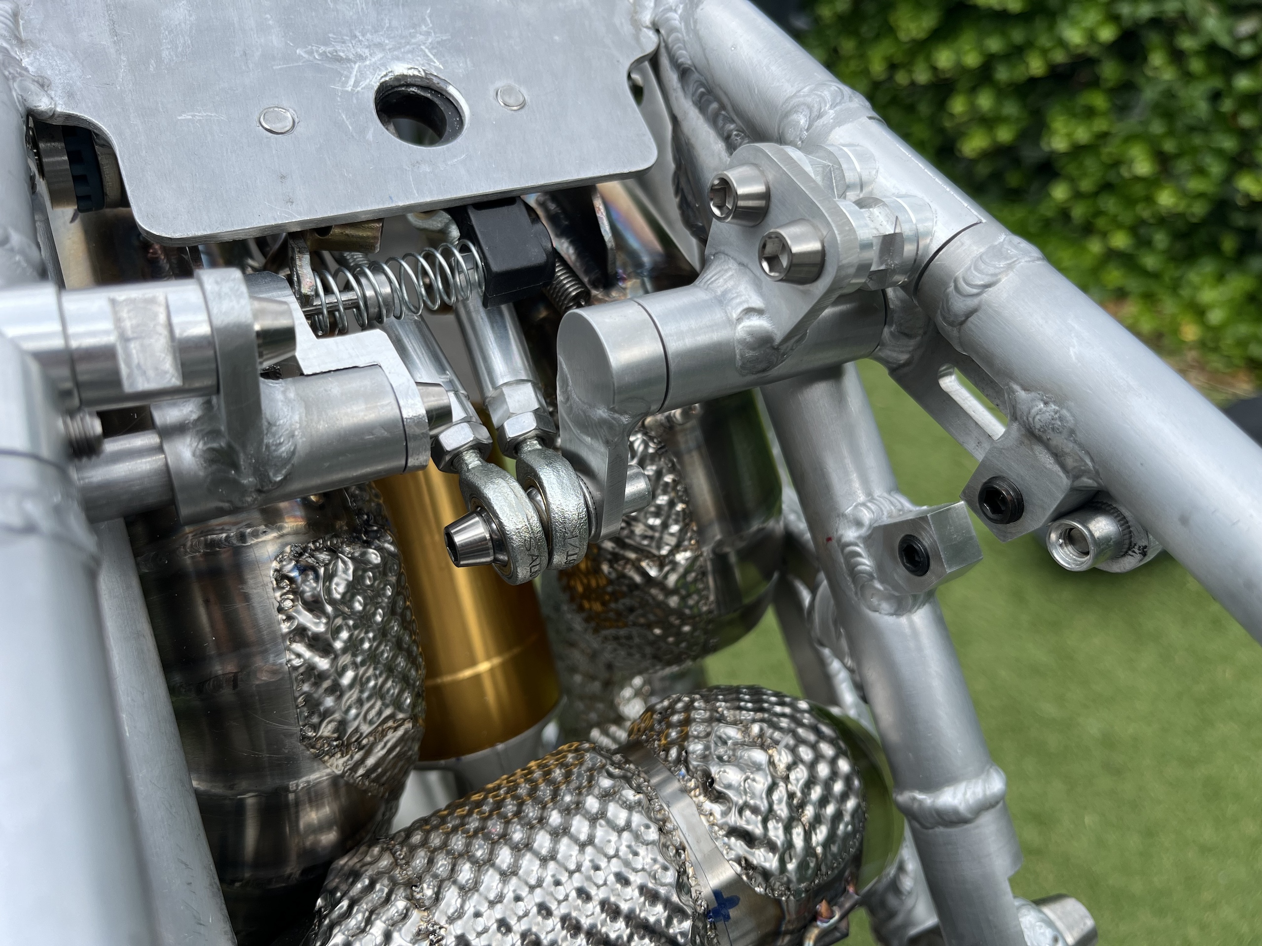
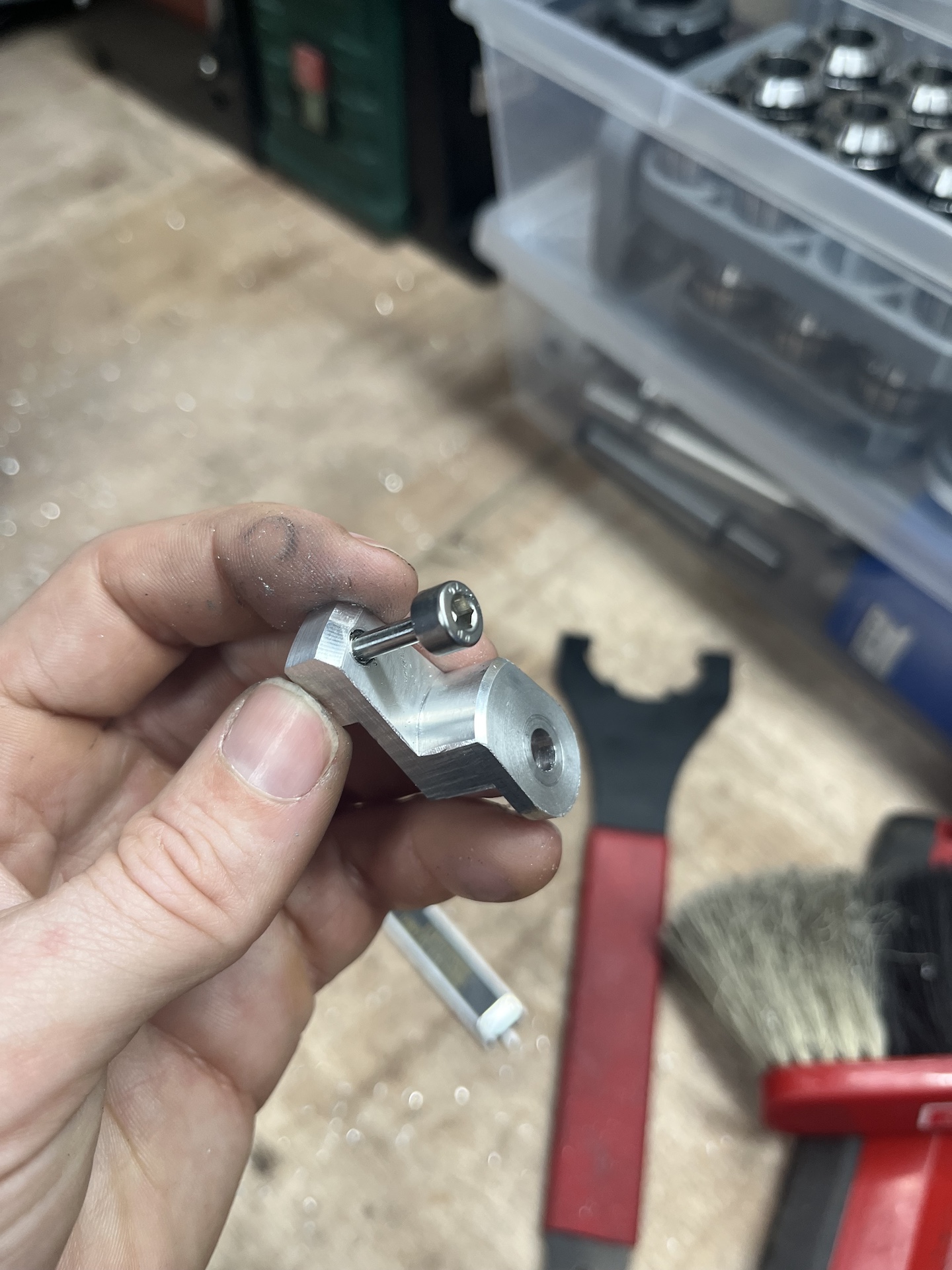
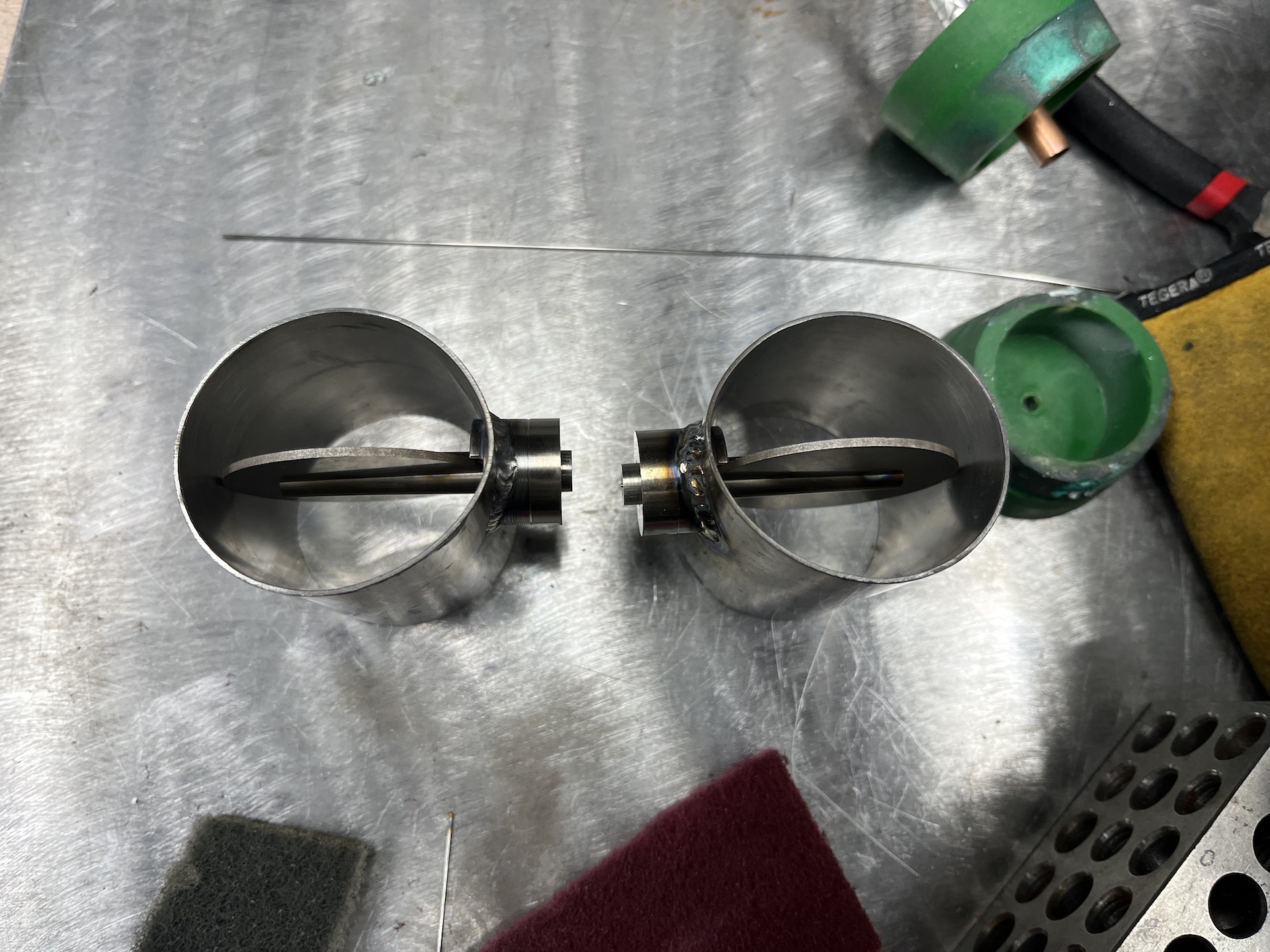
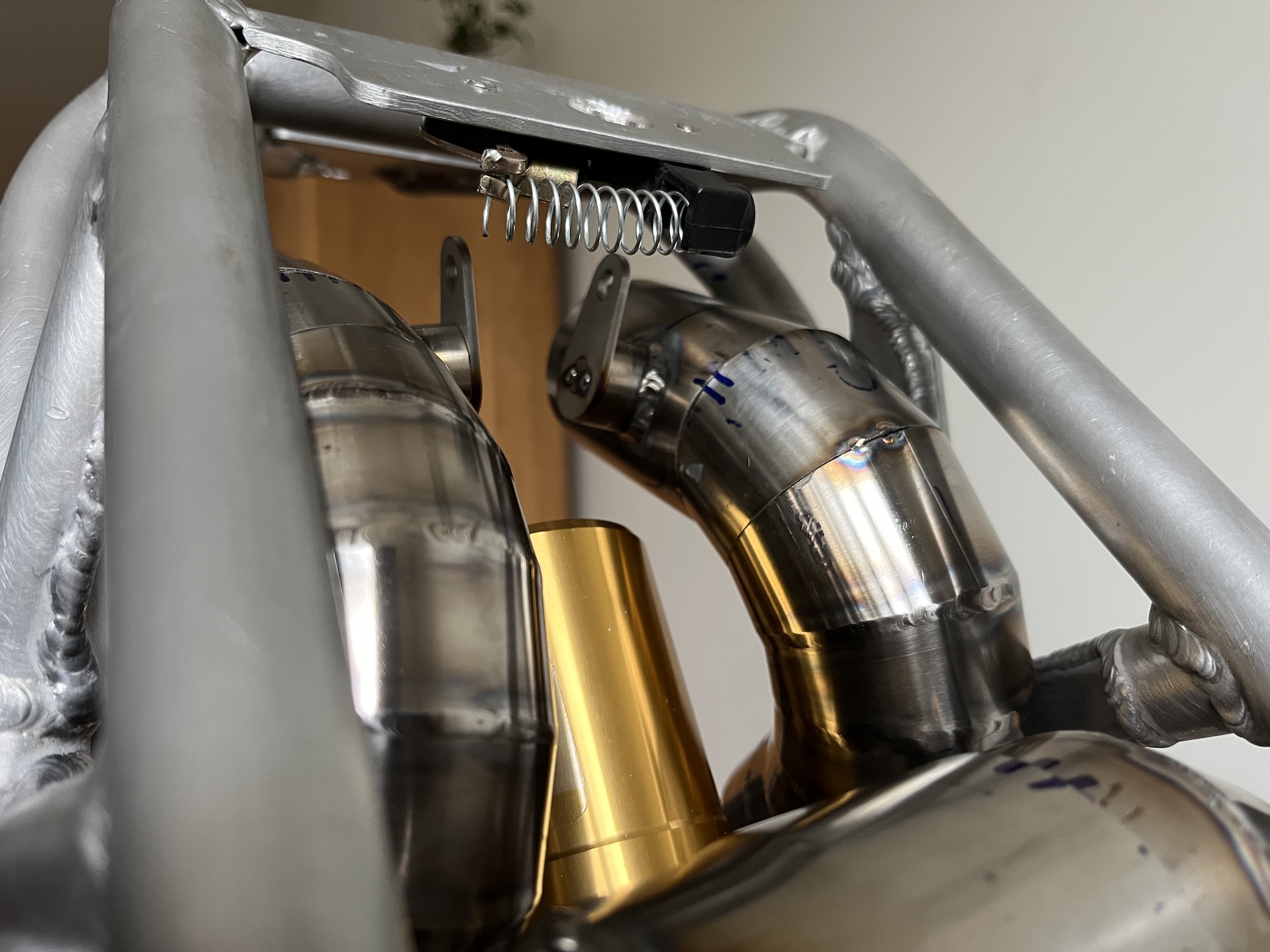
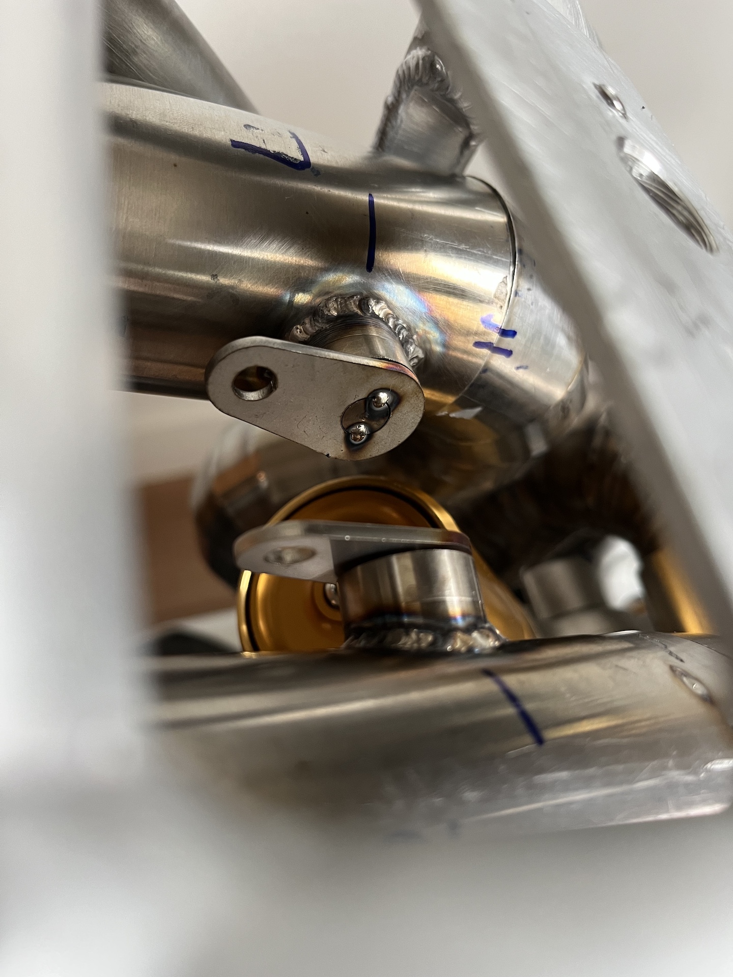
EXHAUST VALVE
Exhaust valve mechanism finished! A latching spring loaded mechanism, that just clicks into place. Very satisfying feel / click! Happy this is done finally.
The purpose of the exhaust valves is for noise reduction when needed. For example an early morning taking into consideration neighbors, pit lane sound check or a police stop…. Not for constant use when riding obviously, and the valves don’t close completely!
Everything is adjustable if it turns out they close to much or little. Works like charm when done correctly, I have used this on multiple bikes, just like Ducati uses it to homologate their bikes.
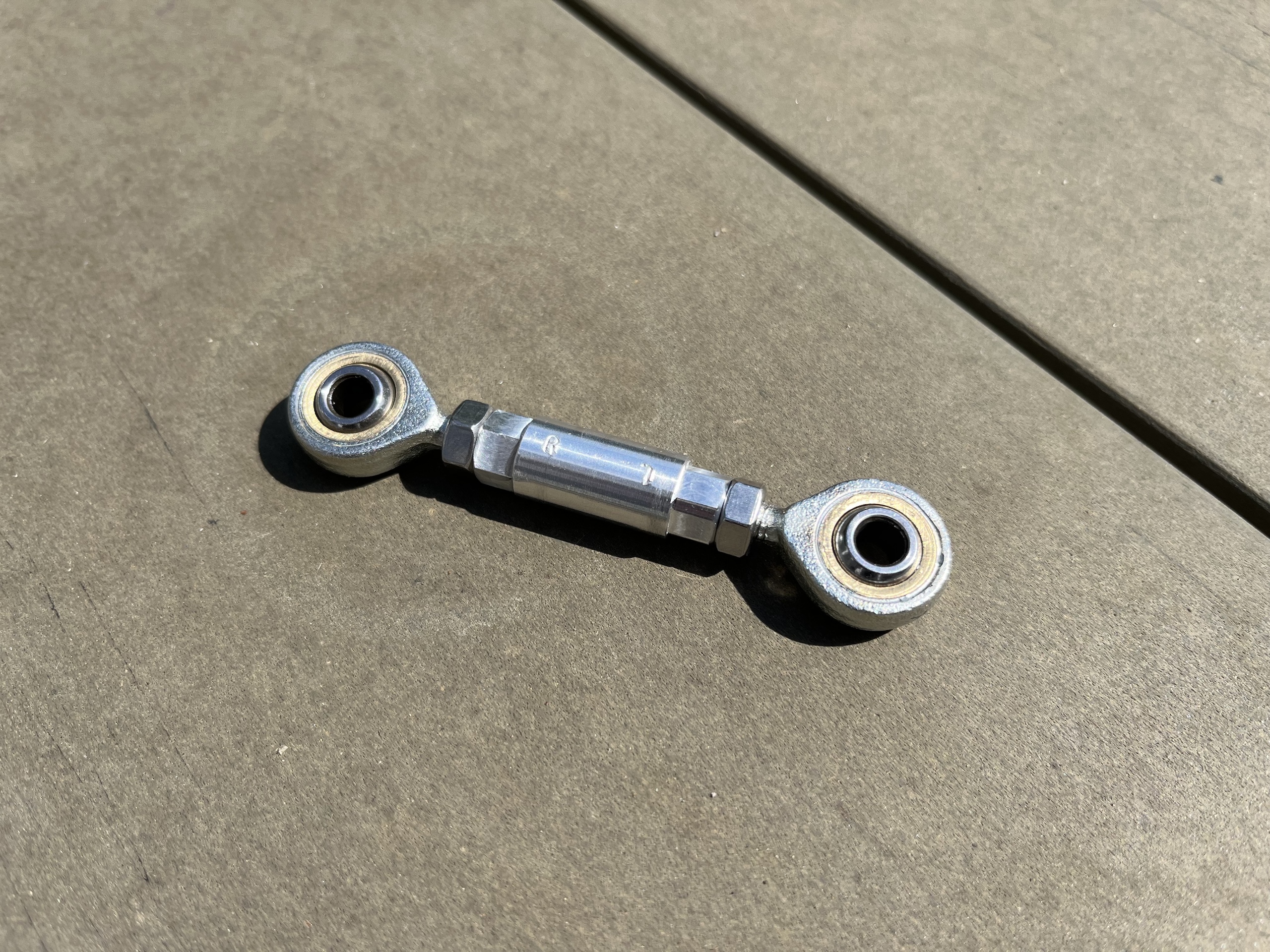
Mechanism is all pretty simple to be honest, but to make it work properly took some trial and error using 3D printed test pieces. The lever clicks into place using spring loaded ball bearing hex screws, and the lever rotates using miniature bearings. The motion is transferred to the valve mechanism using ball joints and adjustment rods.
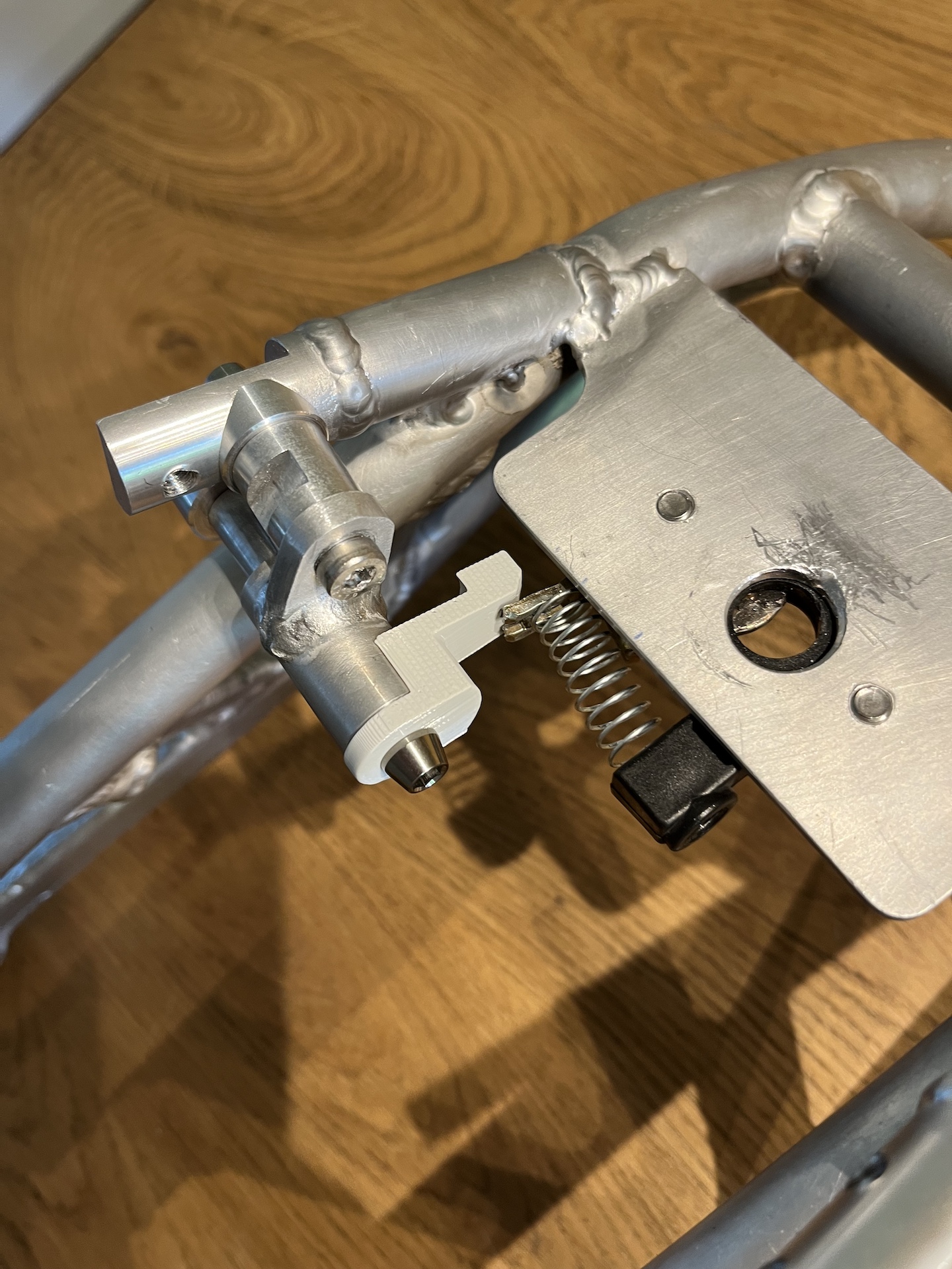
SEAT LATCH
Desmoto seat lock latch mechanism done! Spring loaded and has that extremely satisfying clicky sound and feel.

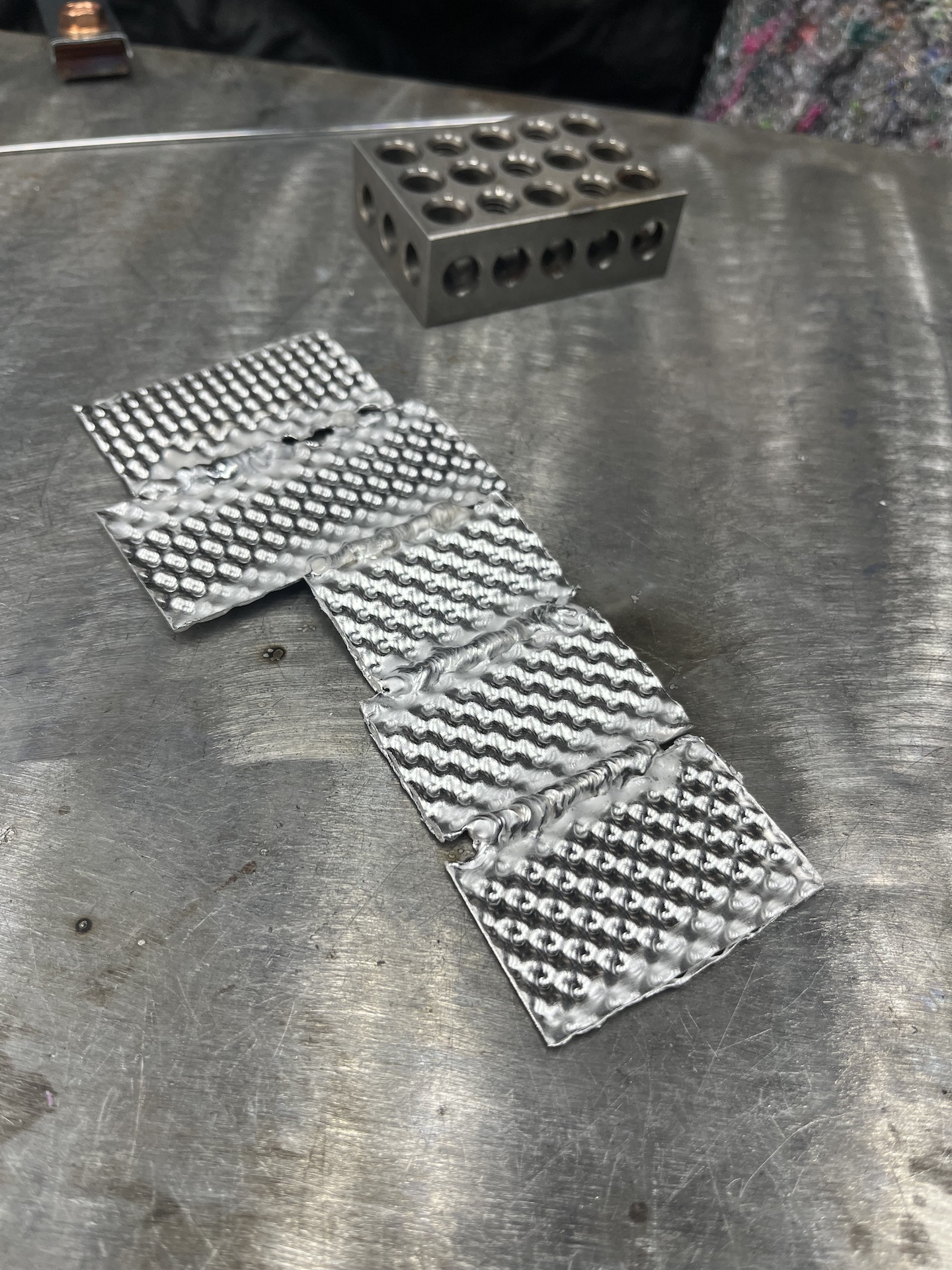
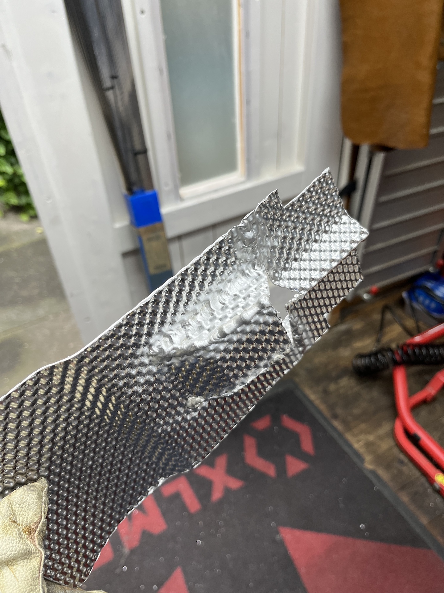
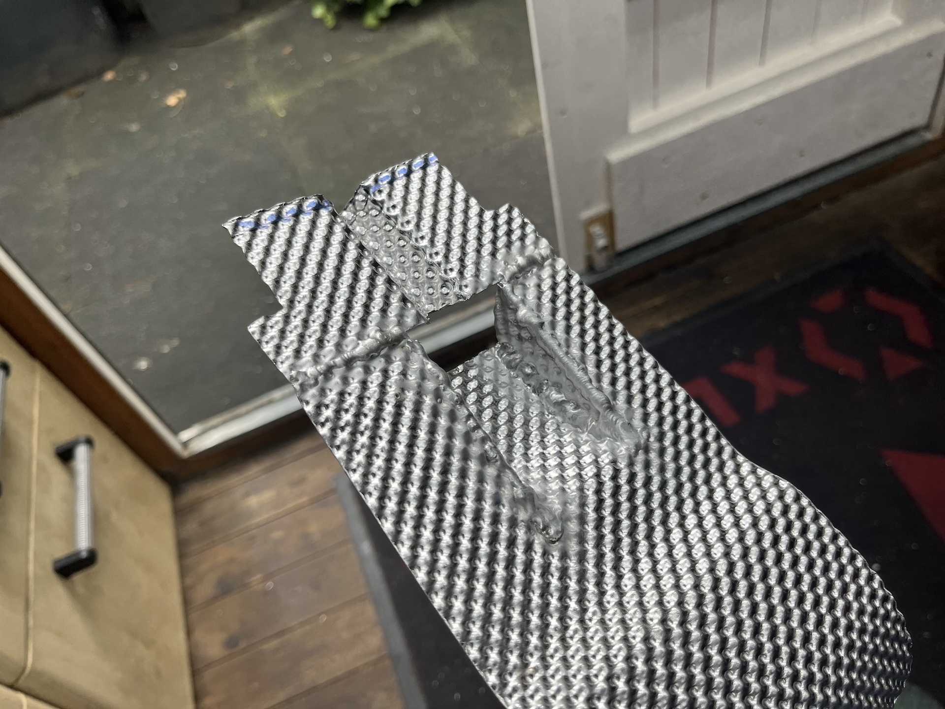
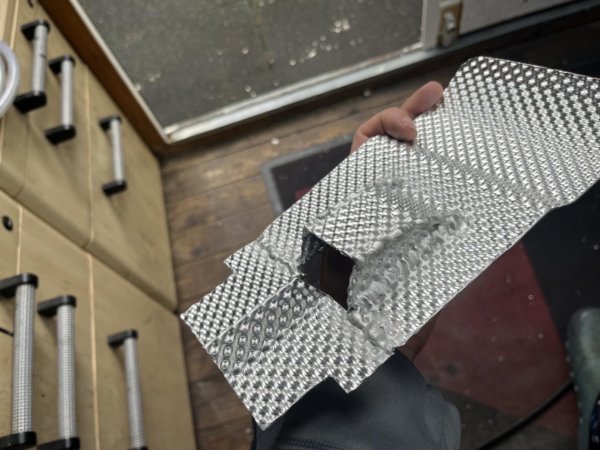
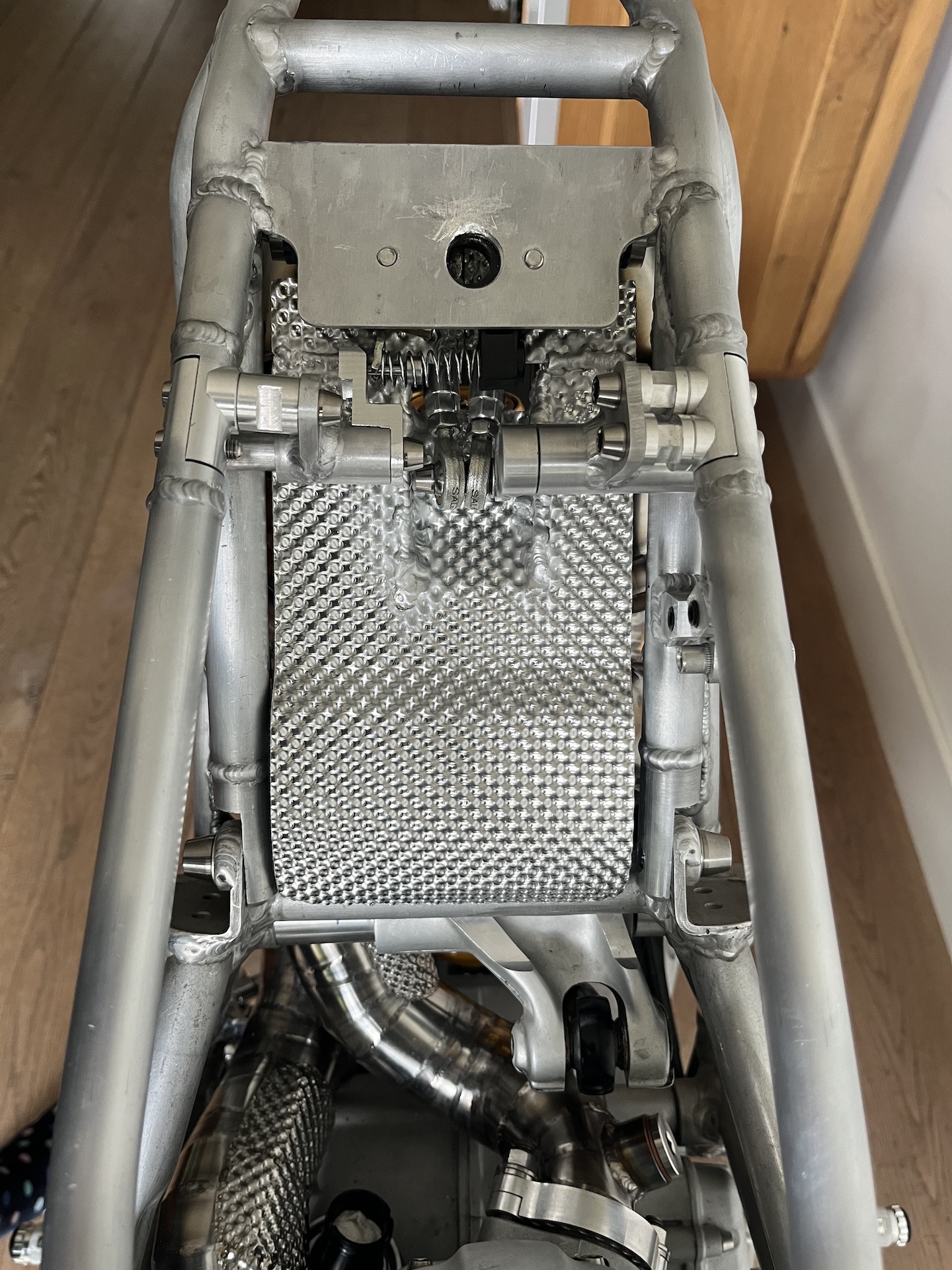
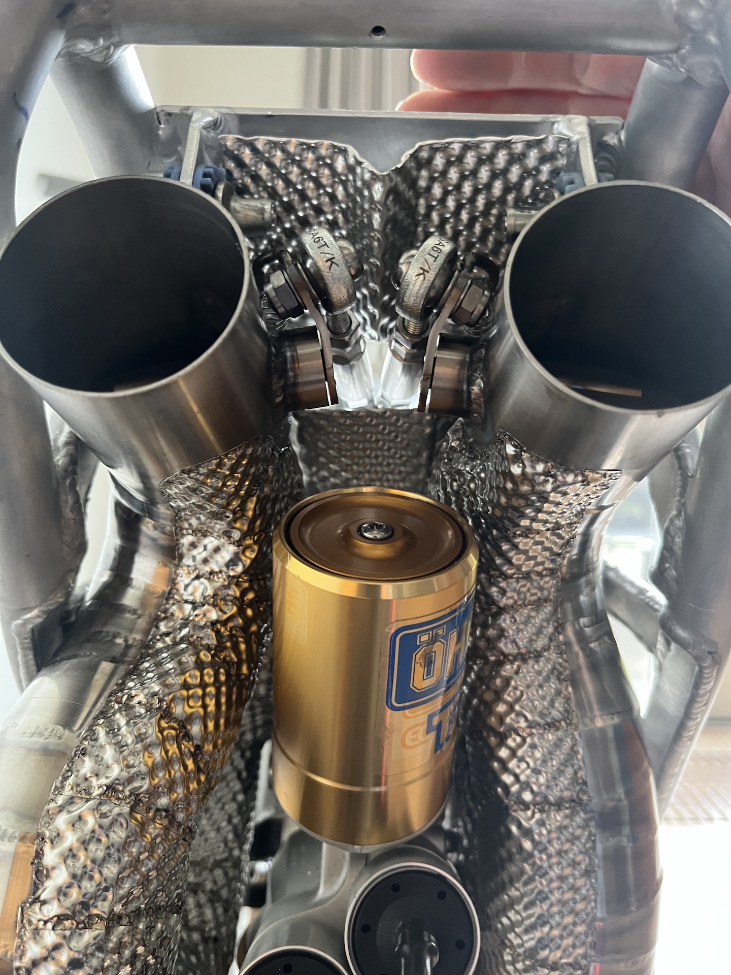
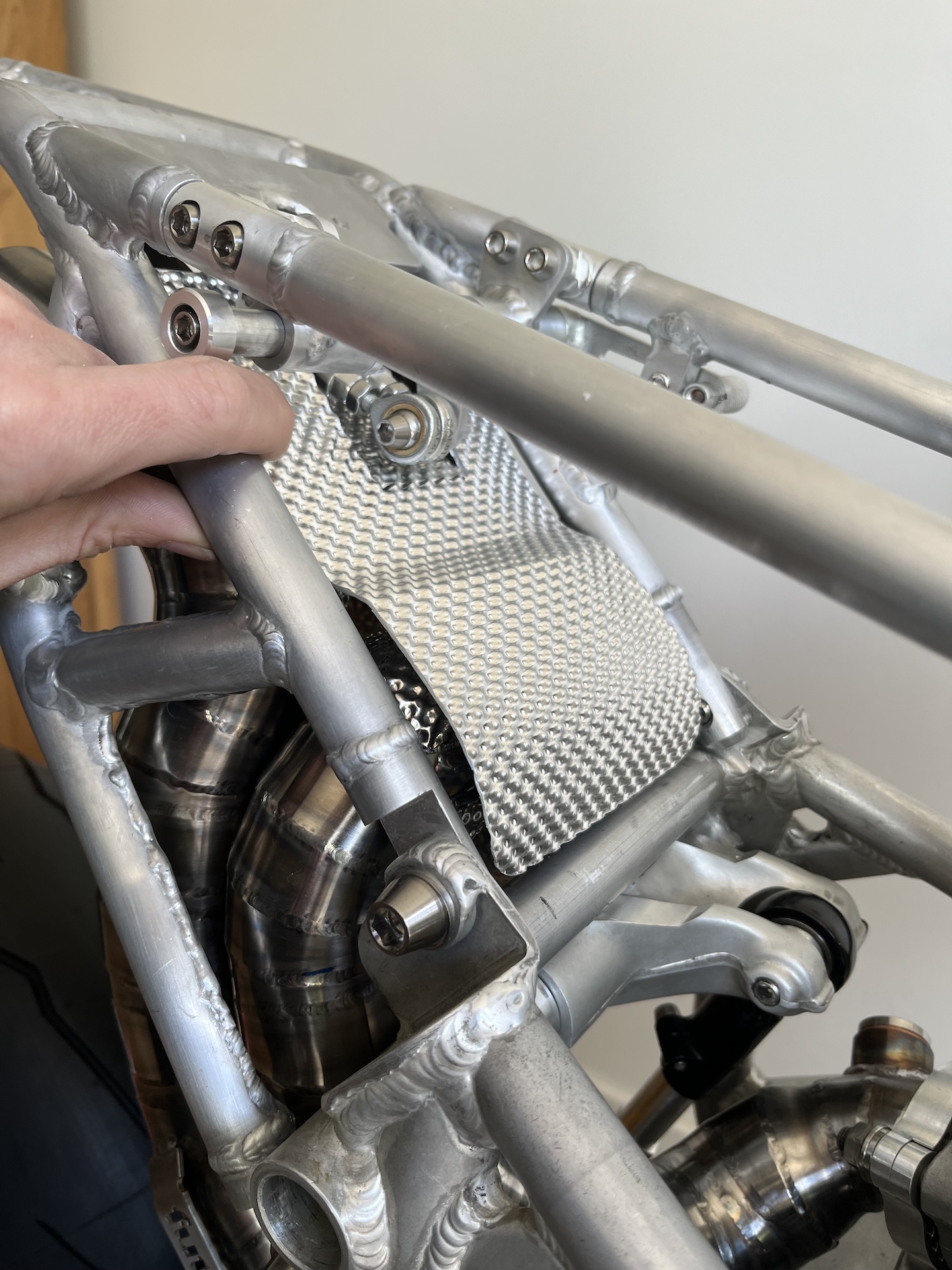
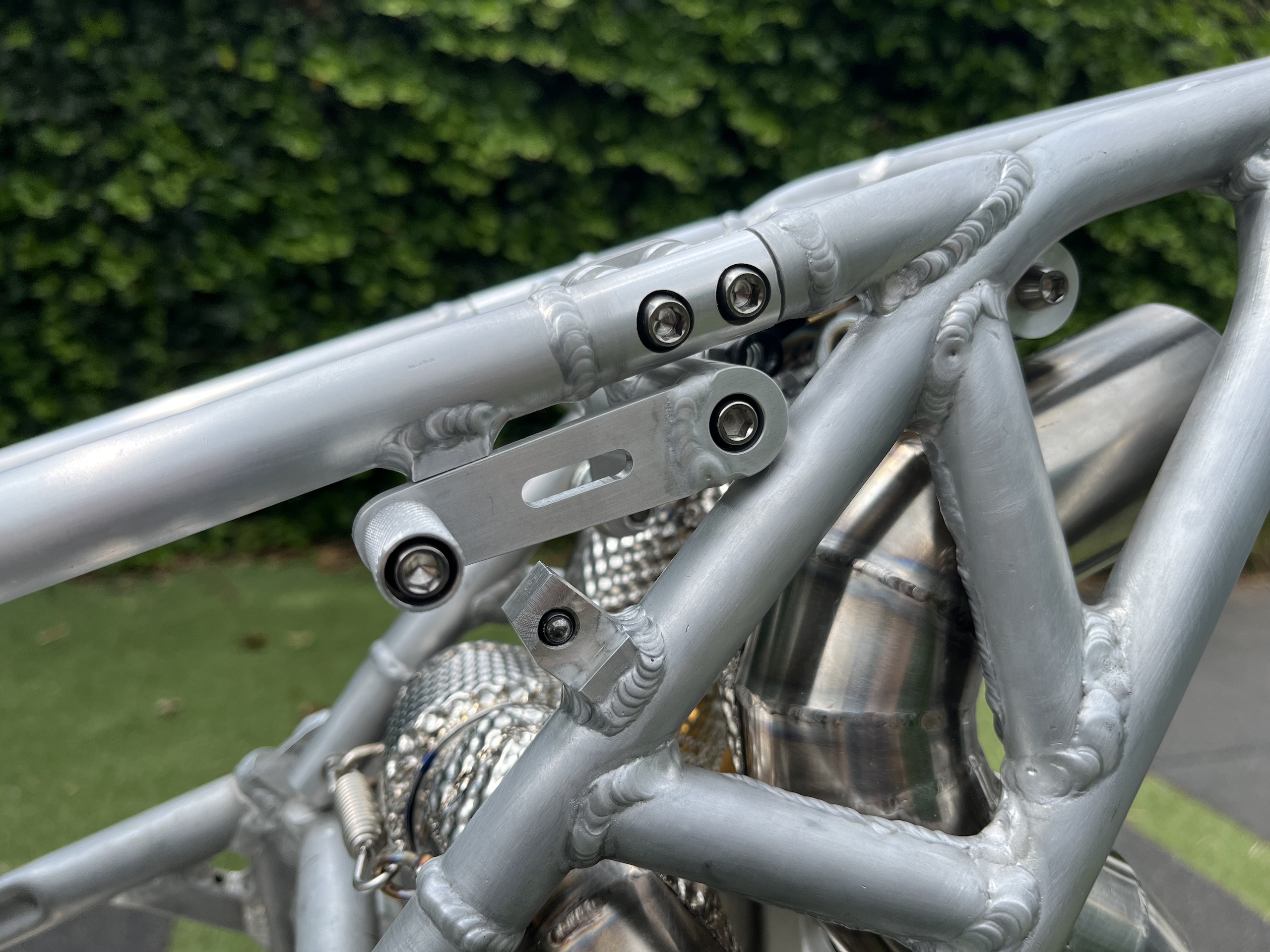
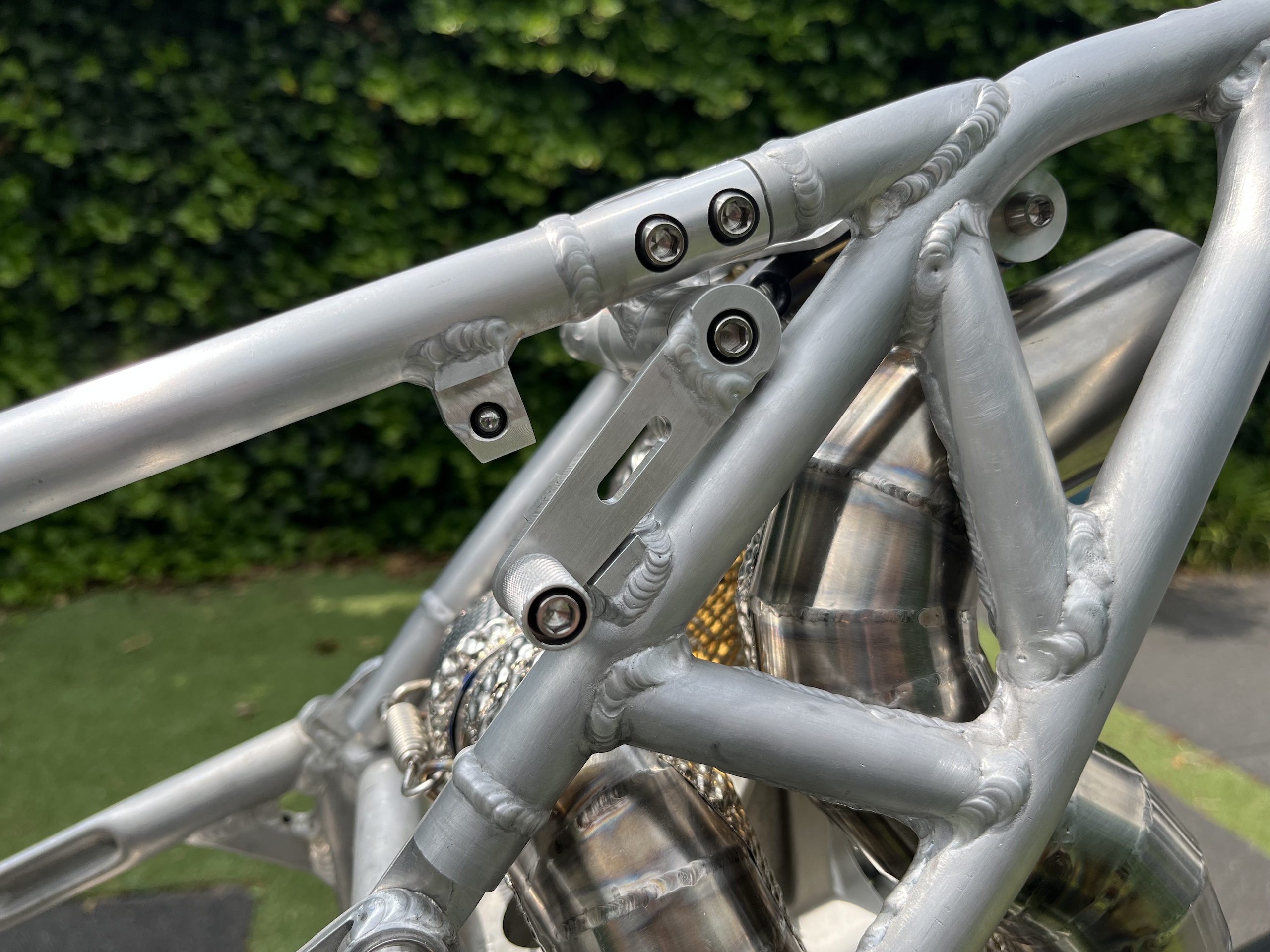
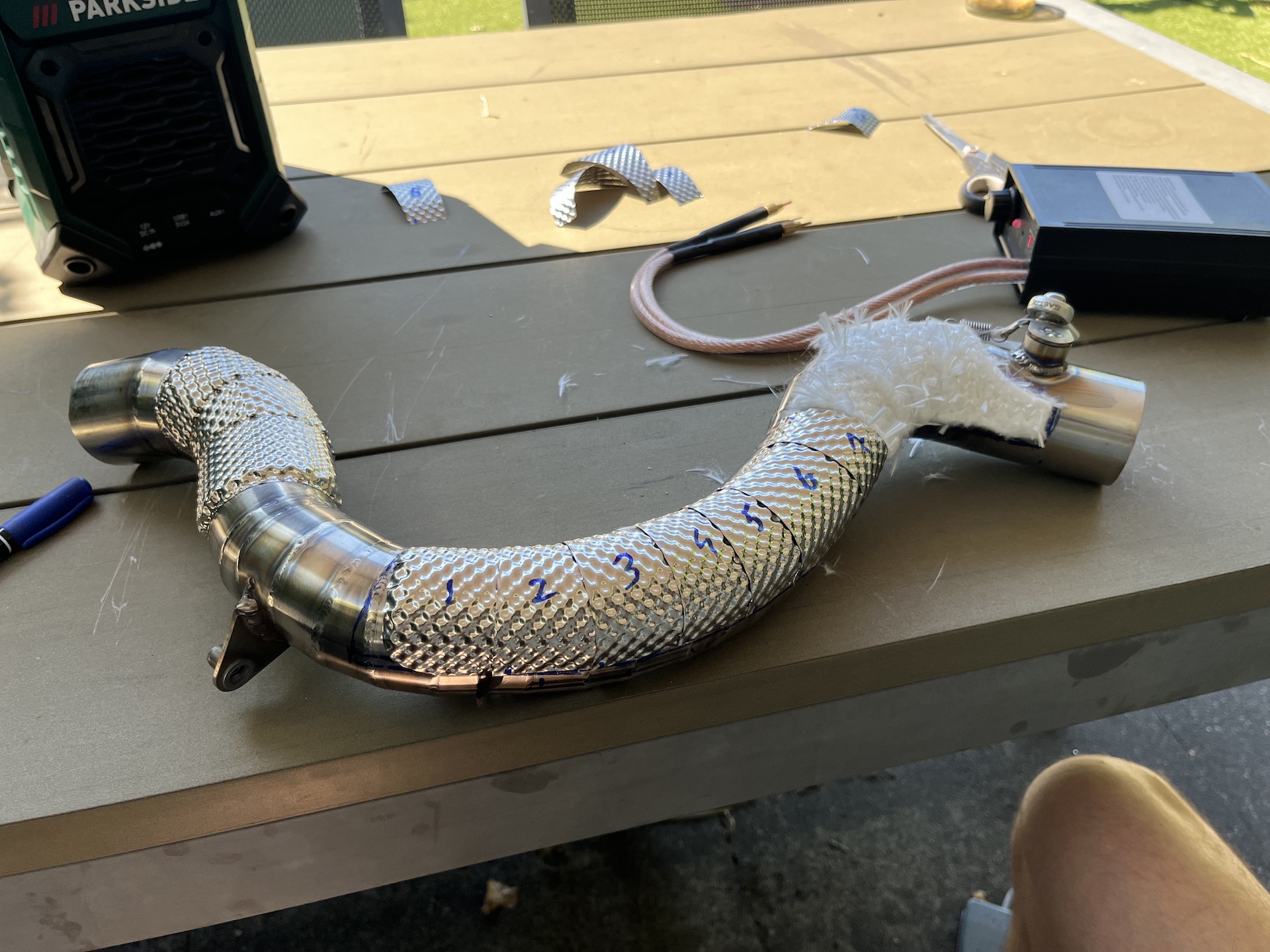
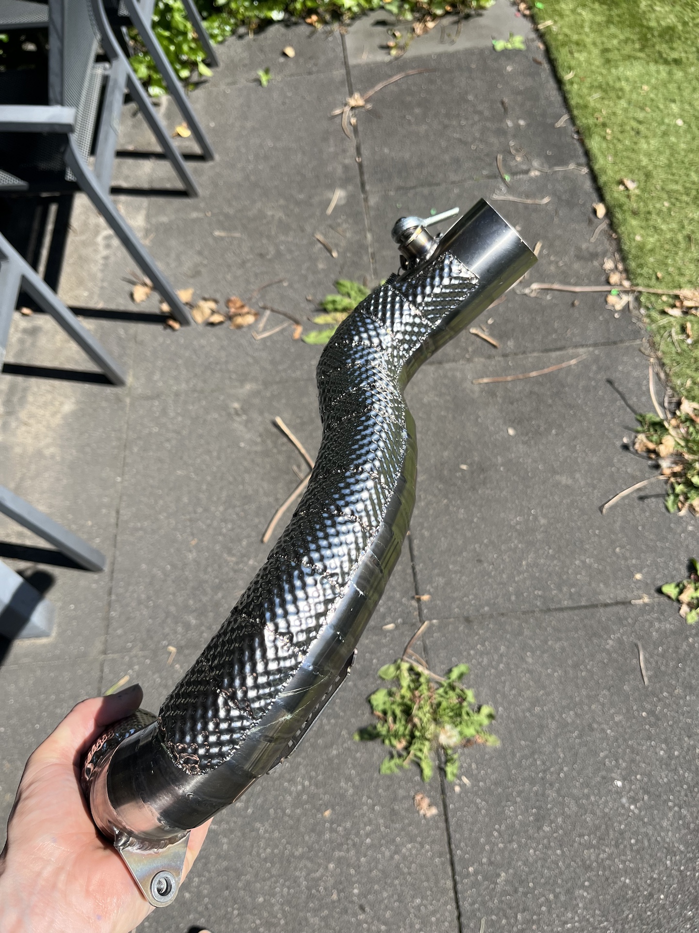
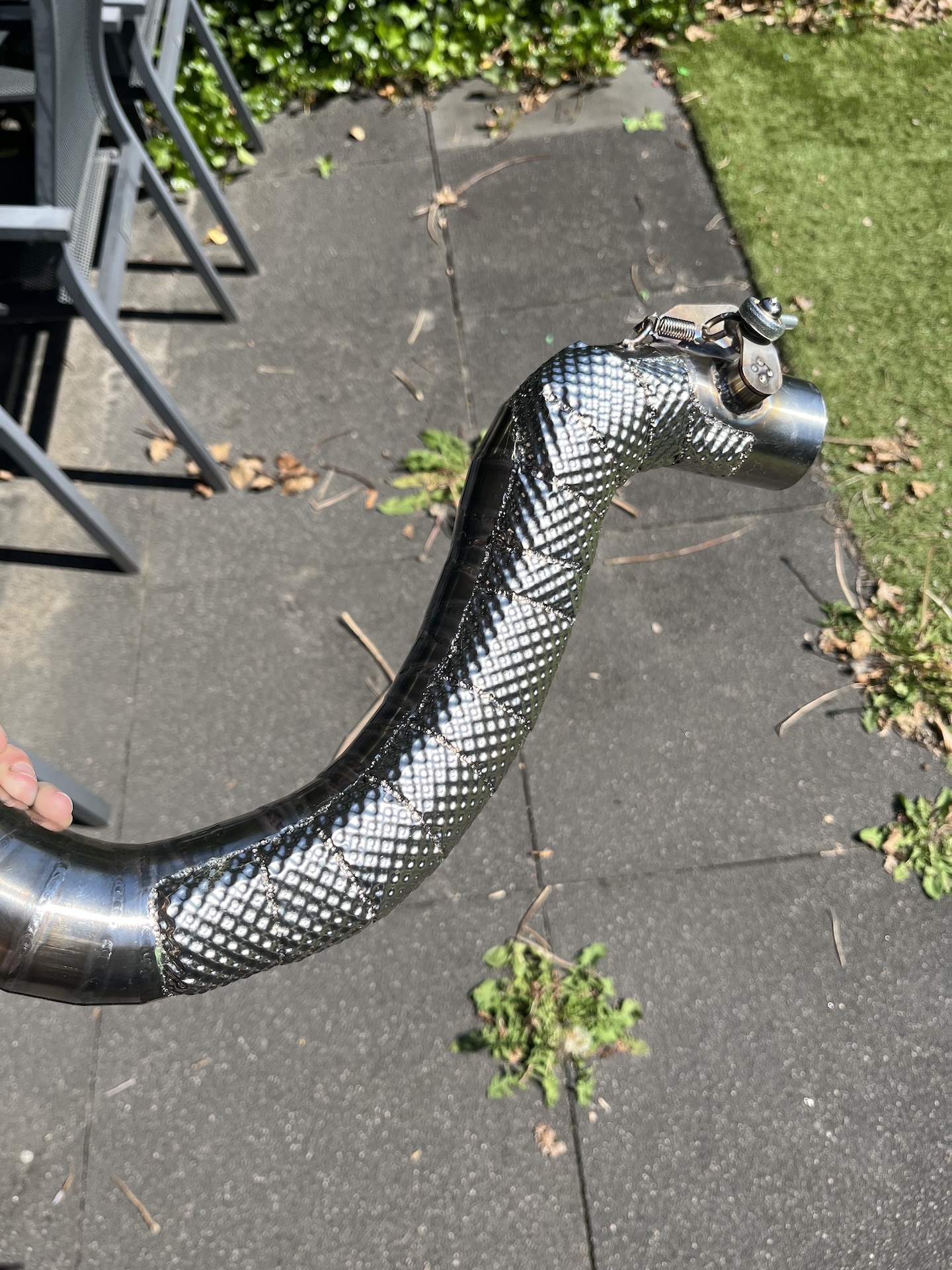
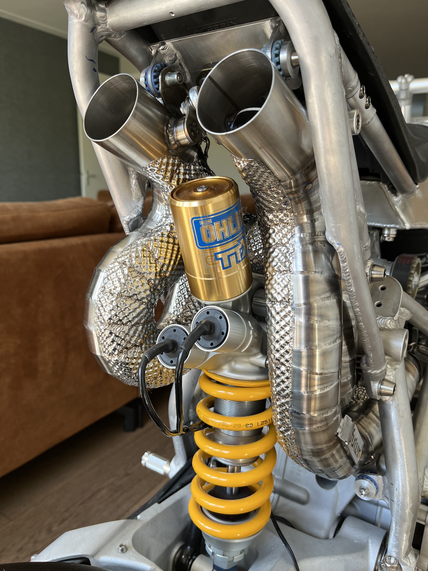
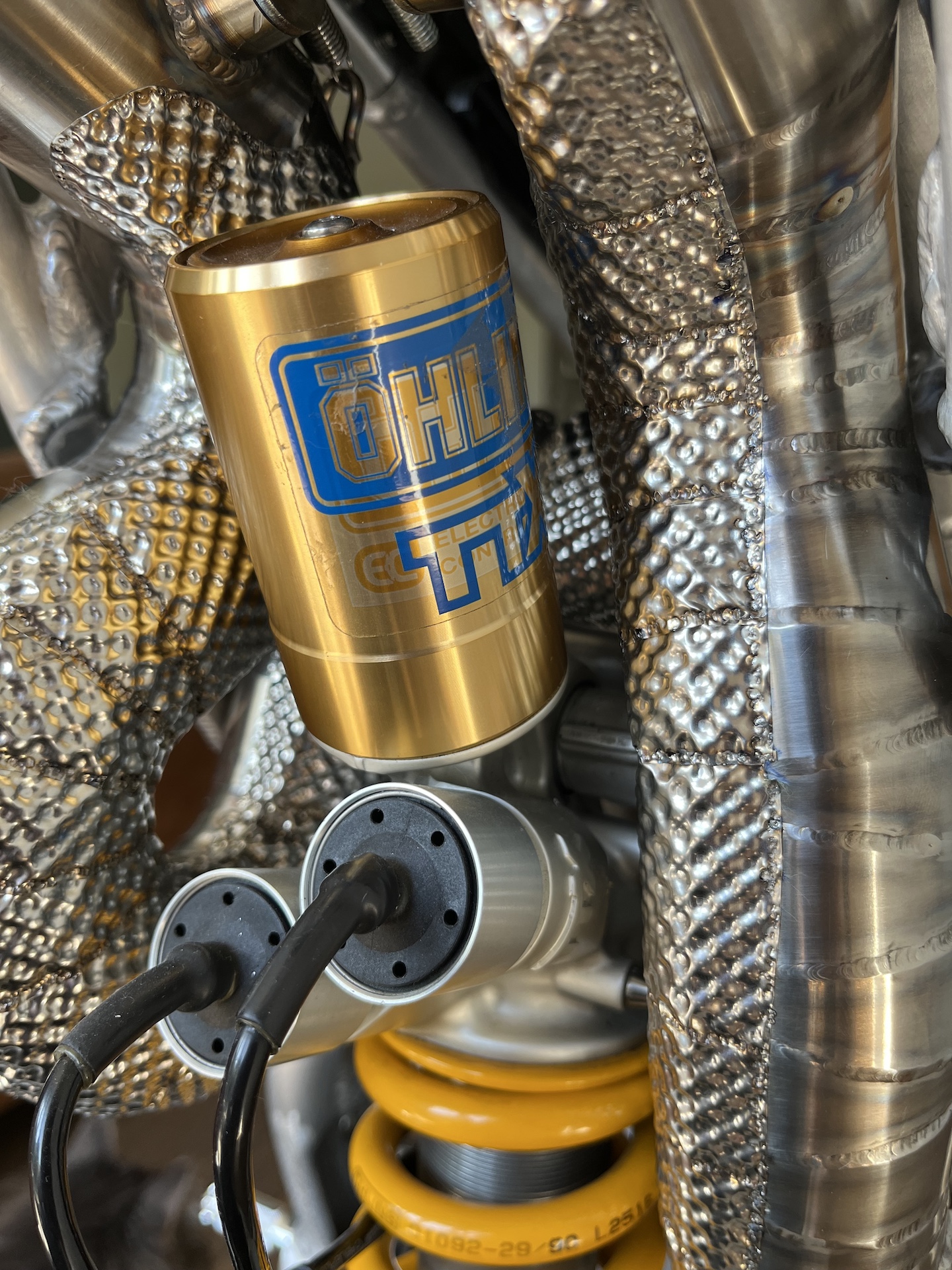
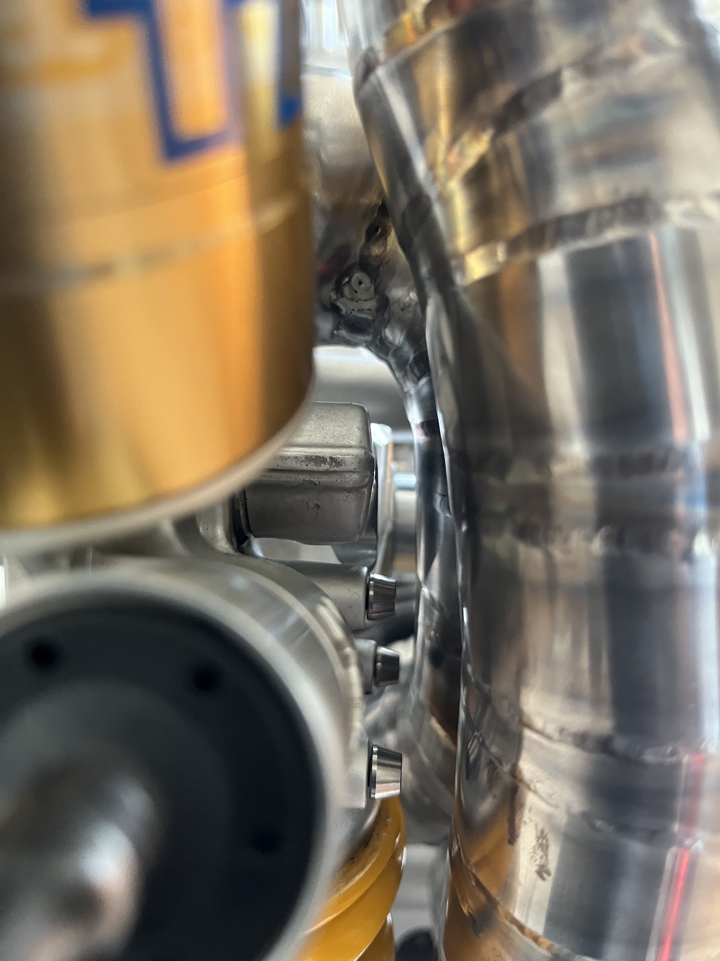
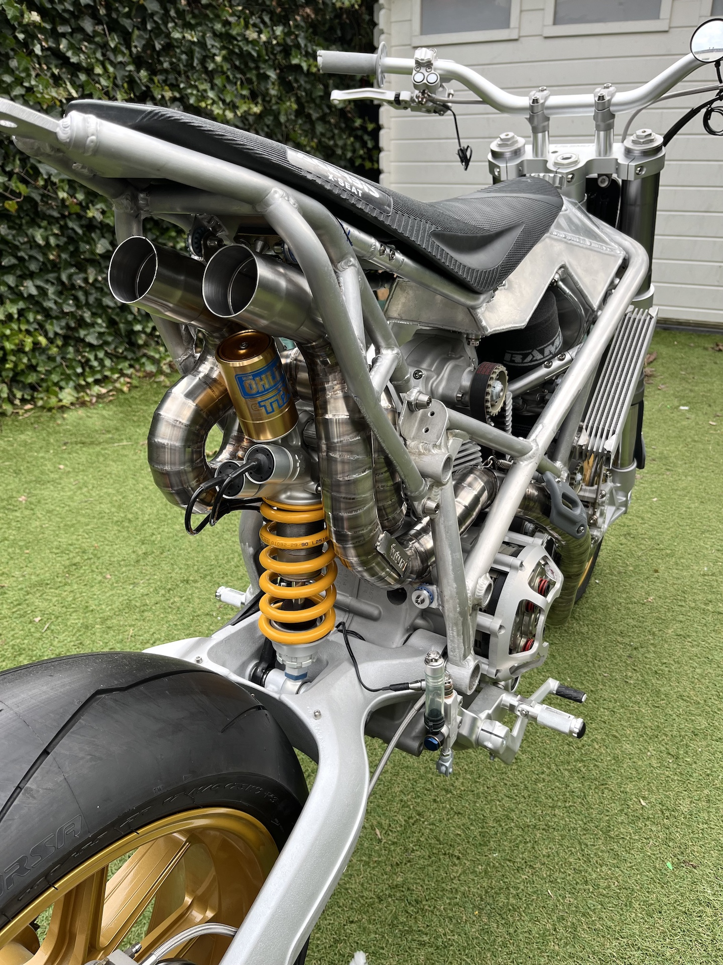
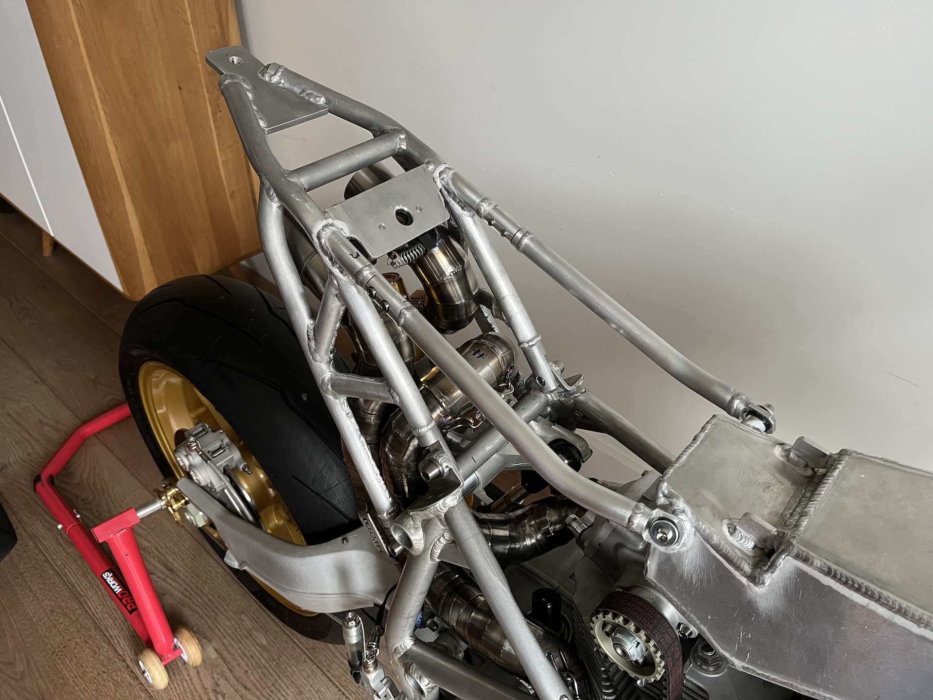
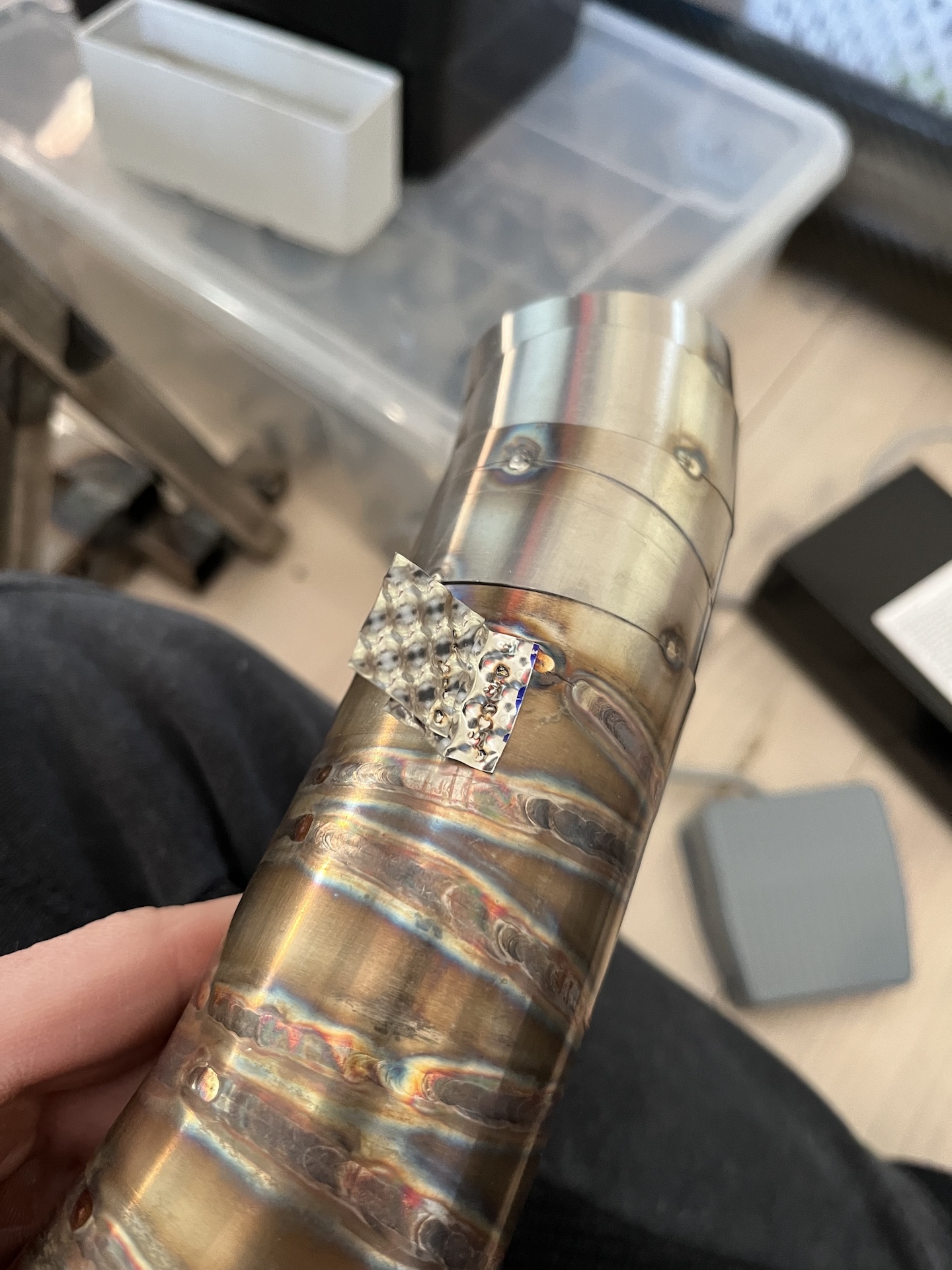
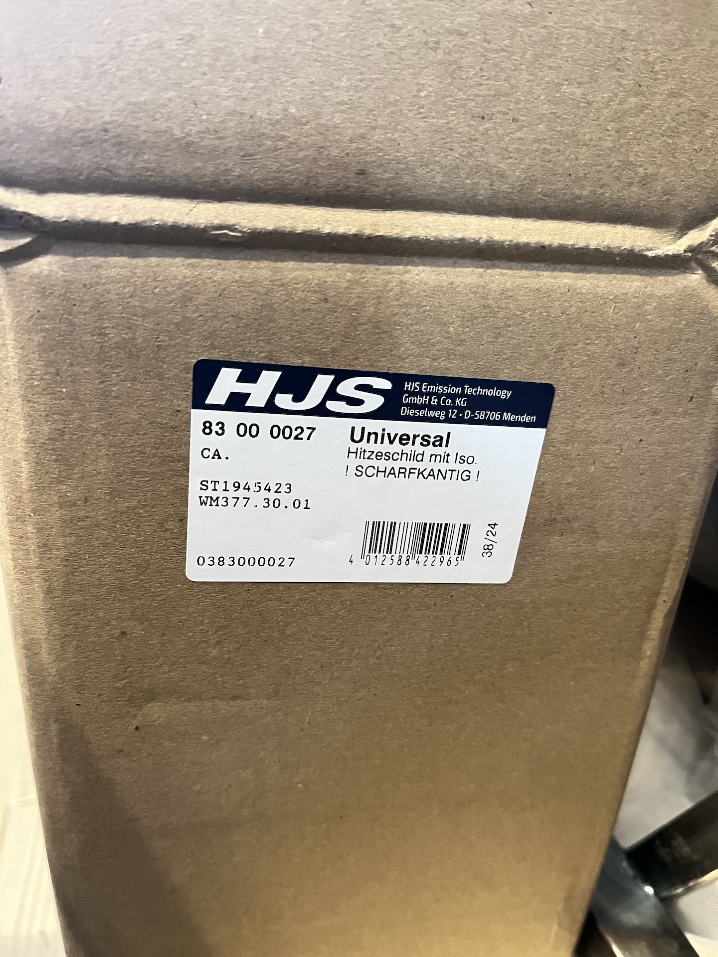
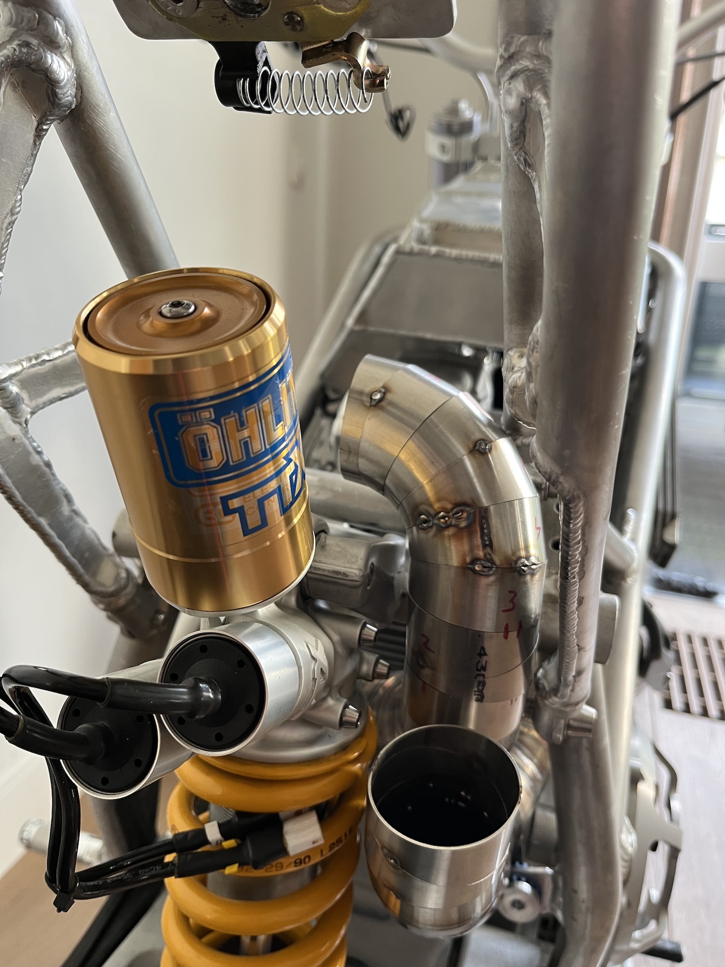
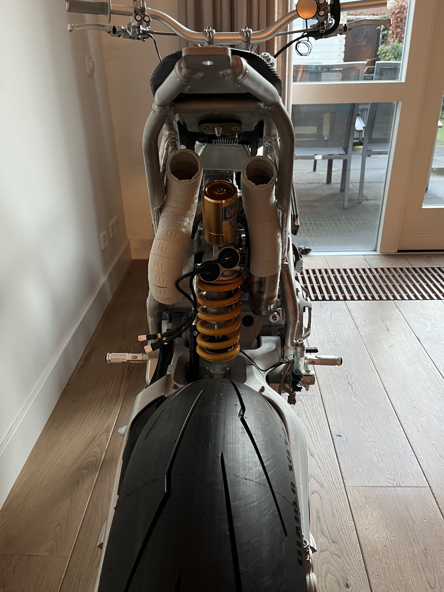
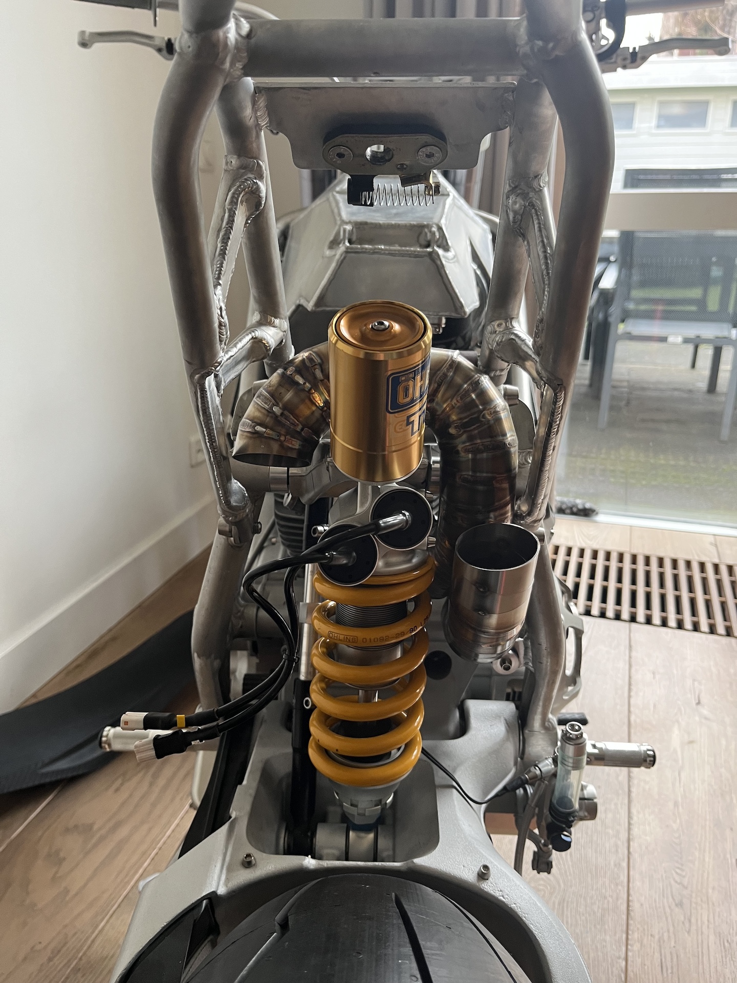
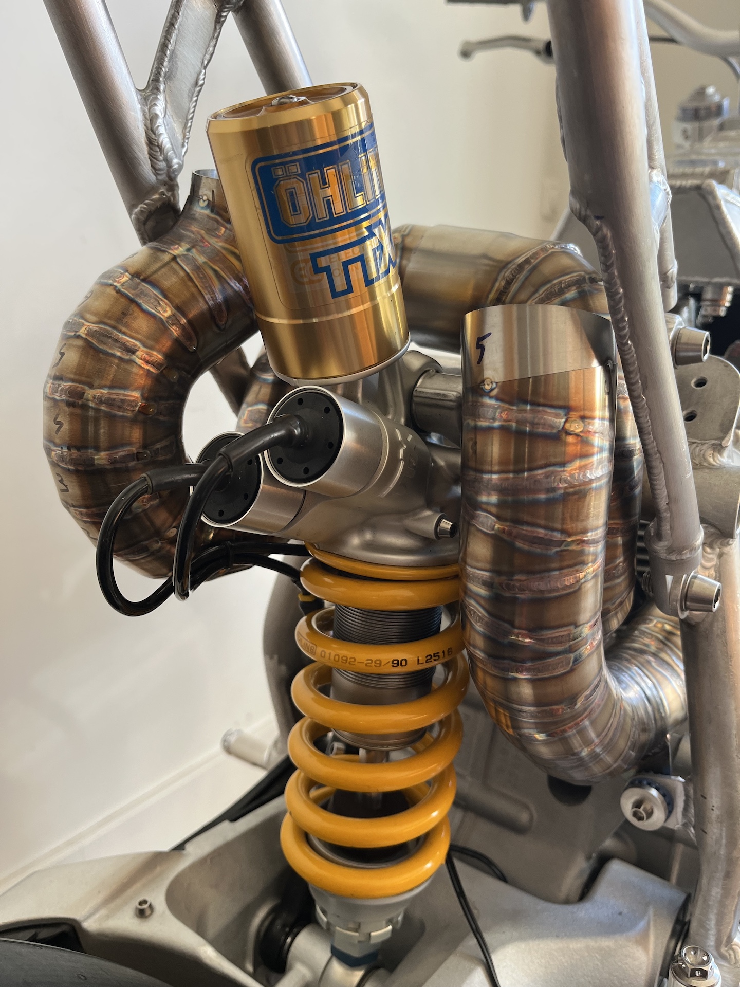
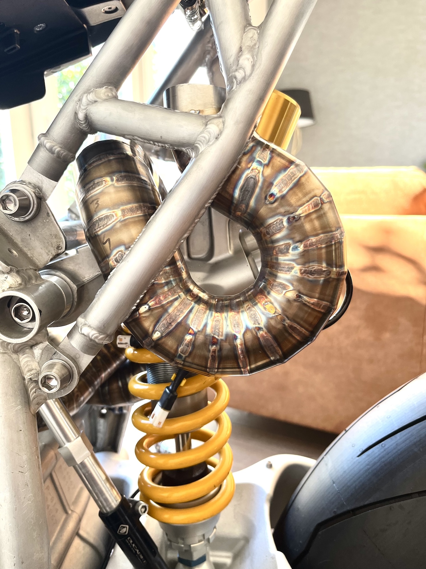
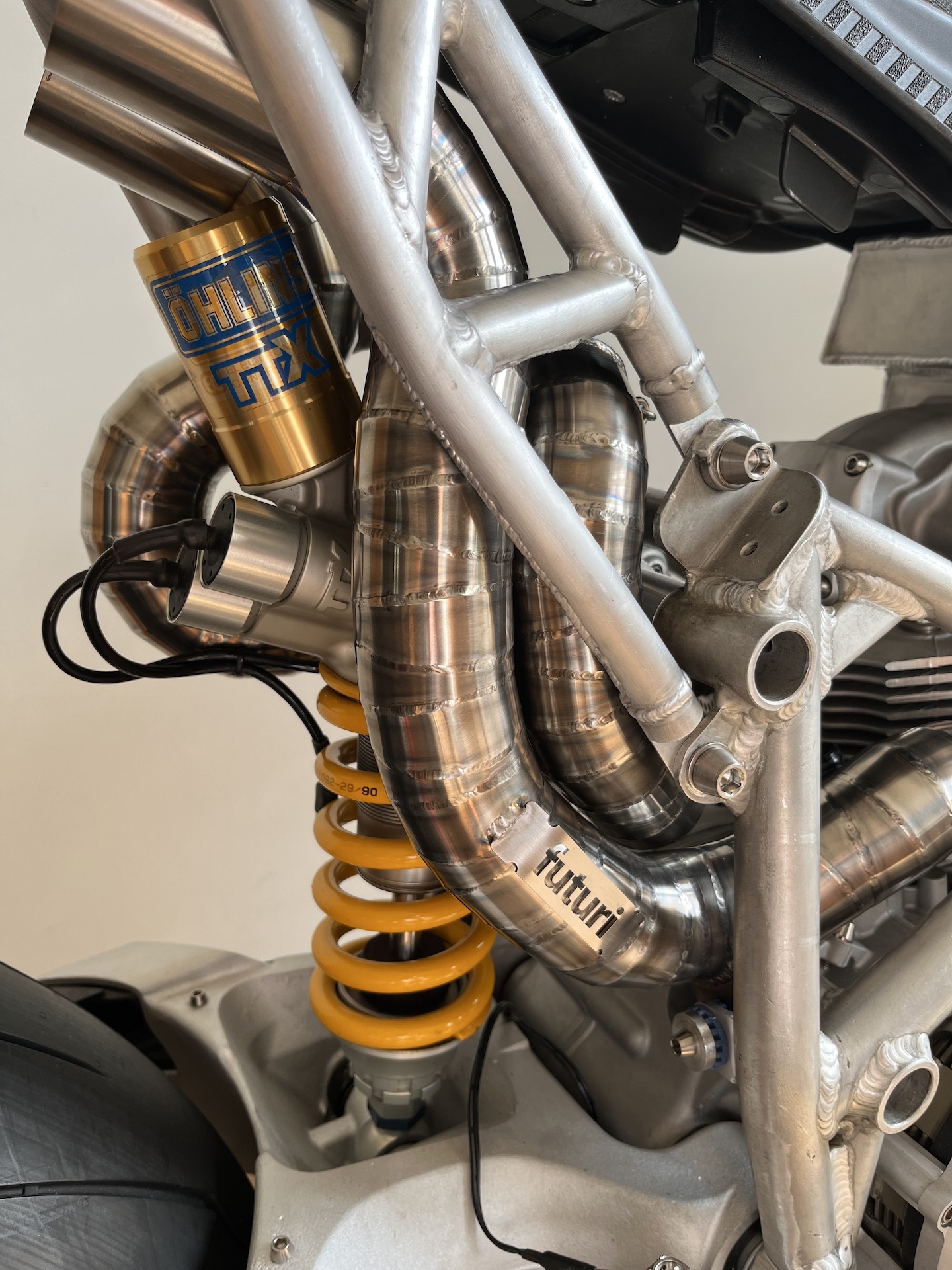
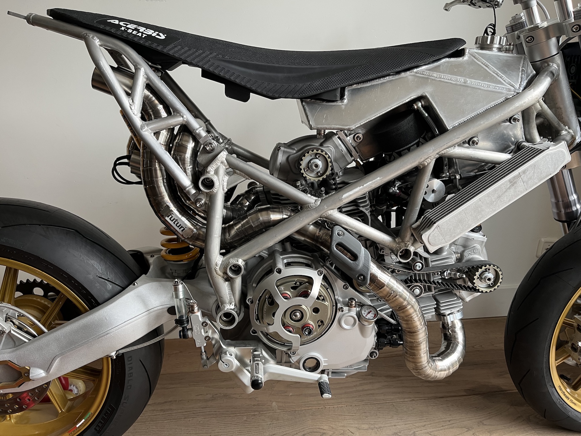
EXHAUST HEAT SHIELDING
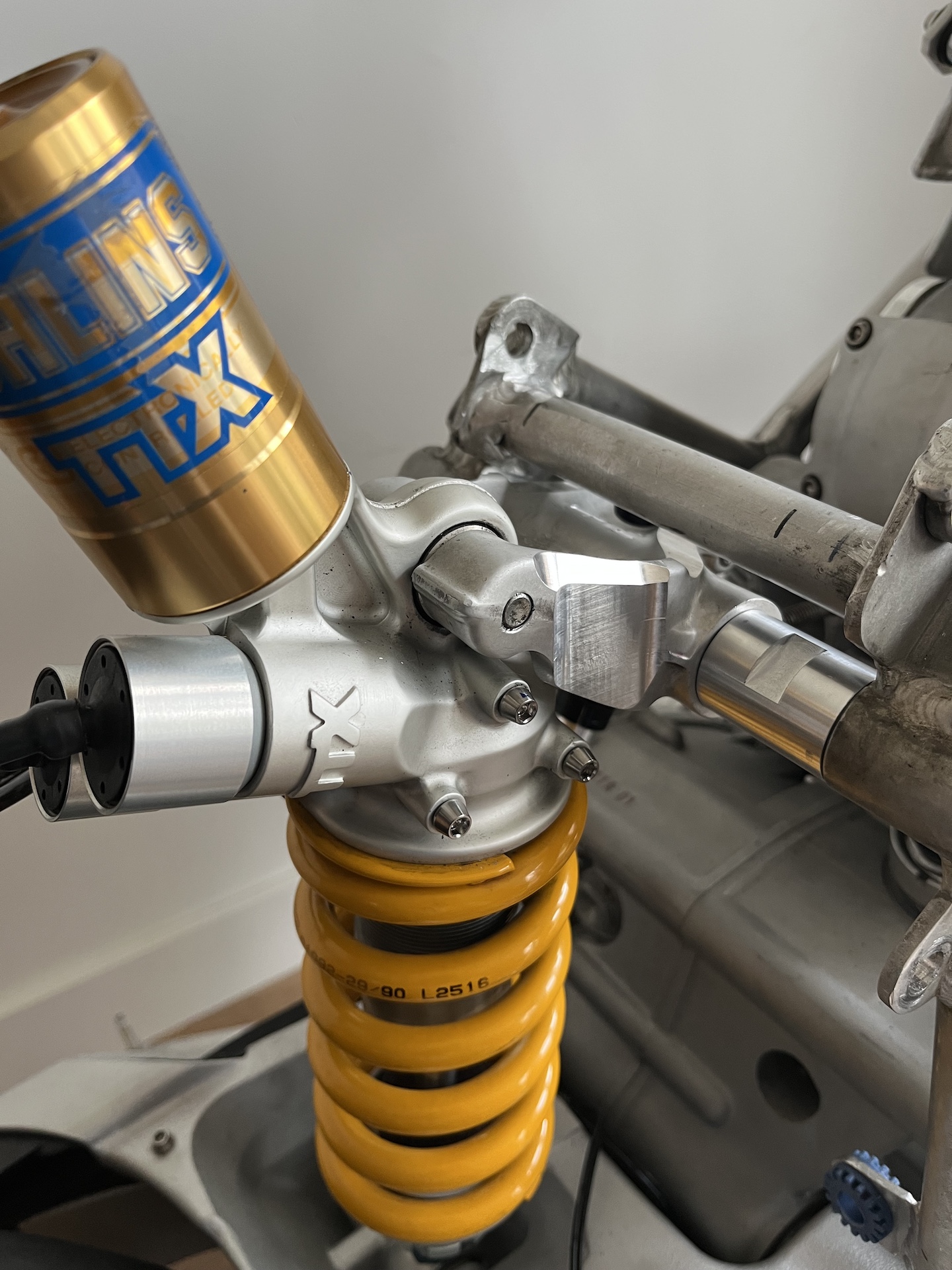
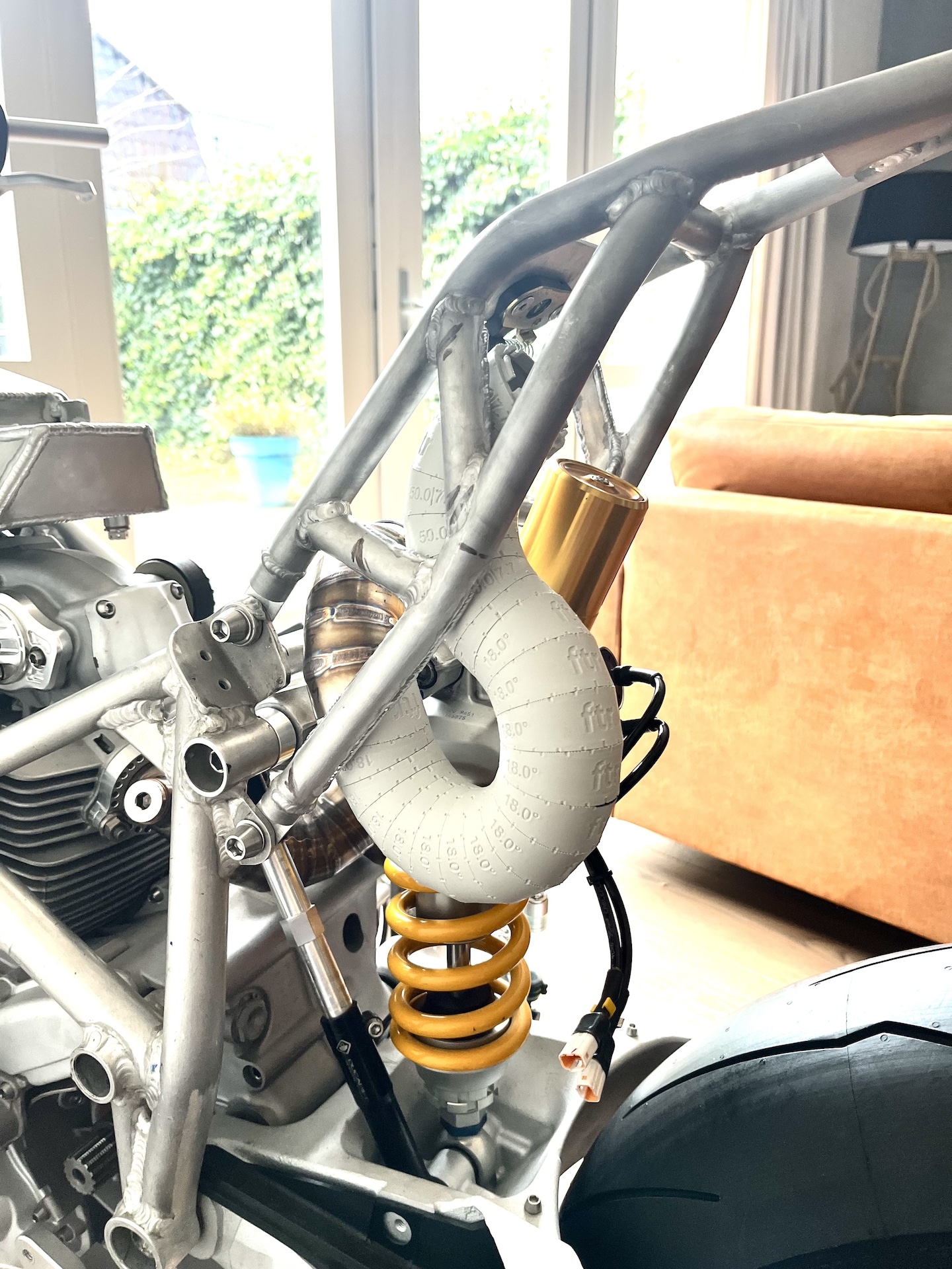
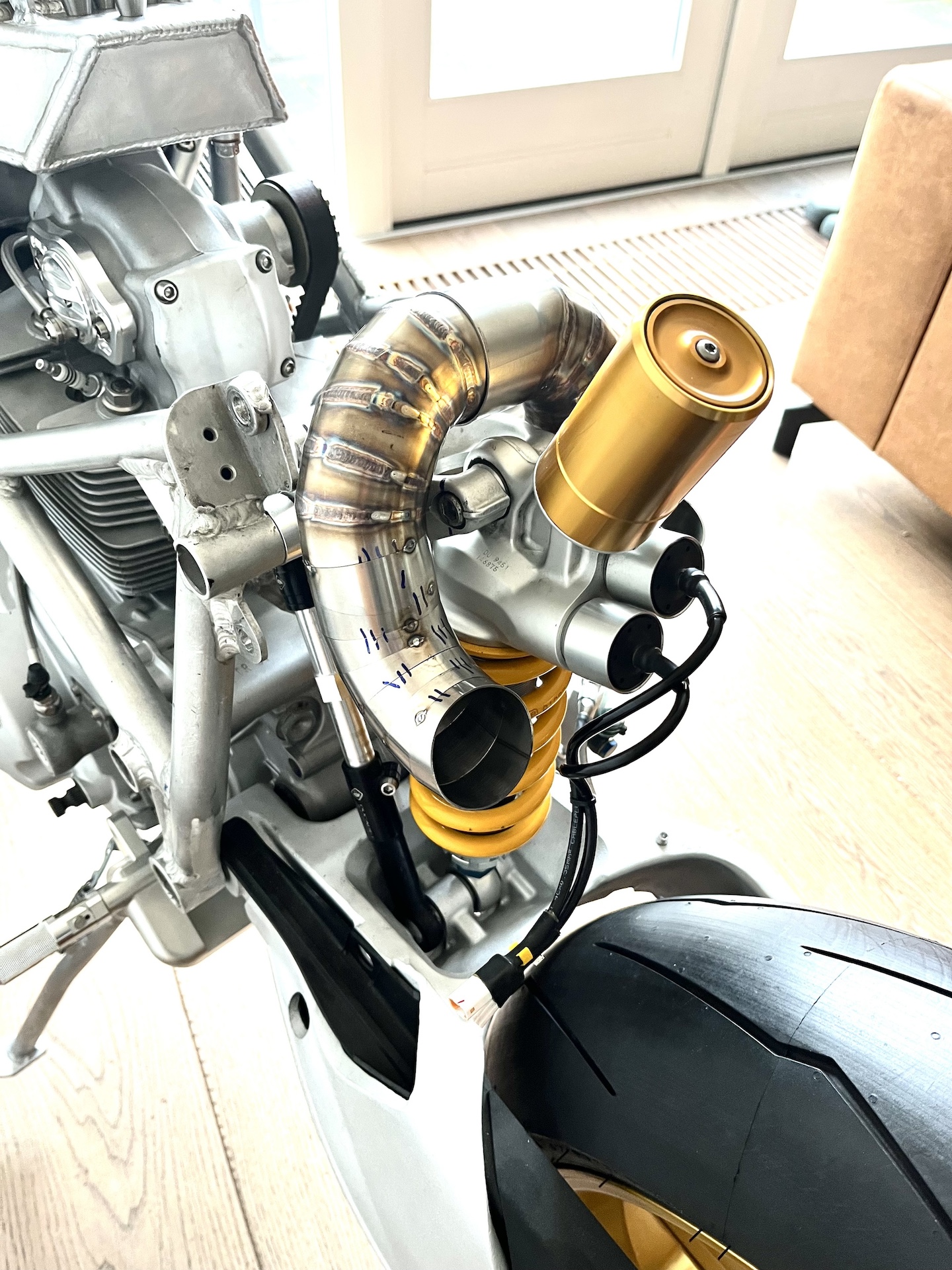
For all the people worried about the Öhlins TTX rear shock! Exhaust heat shielding ✅
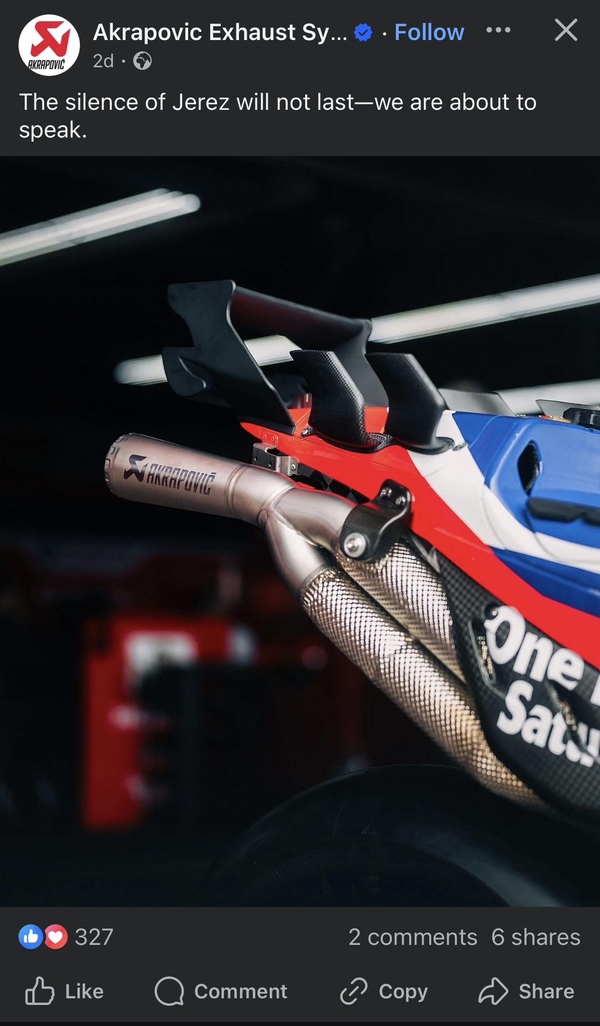
Took a very long time… Simply also because I didn’t like building these shields. 90% less radiation heat! Same method as used in MotoGP and high-end racing cars. Hopefully this satisfies all the people so worried about the rear shock.
Worst case scenario I have 2 extra options left. Partially cover the shock in heat reflecting fiber tape and add a ceramic sock to the oil reservoir.


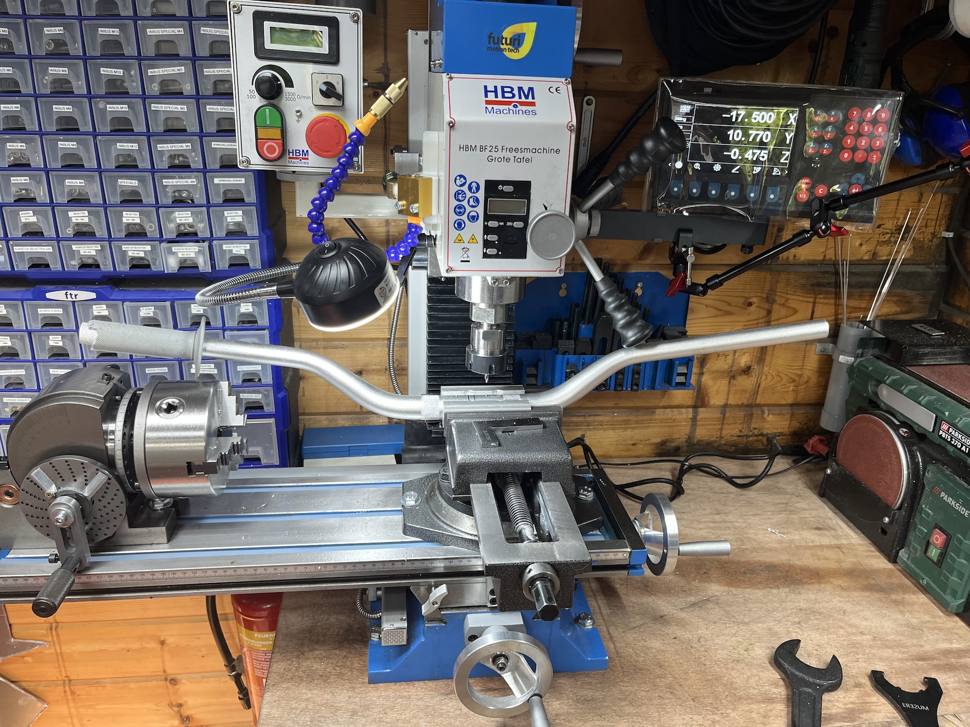
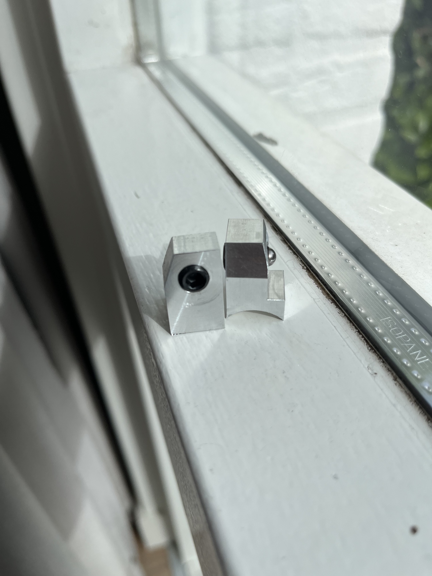
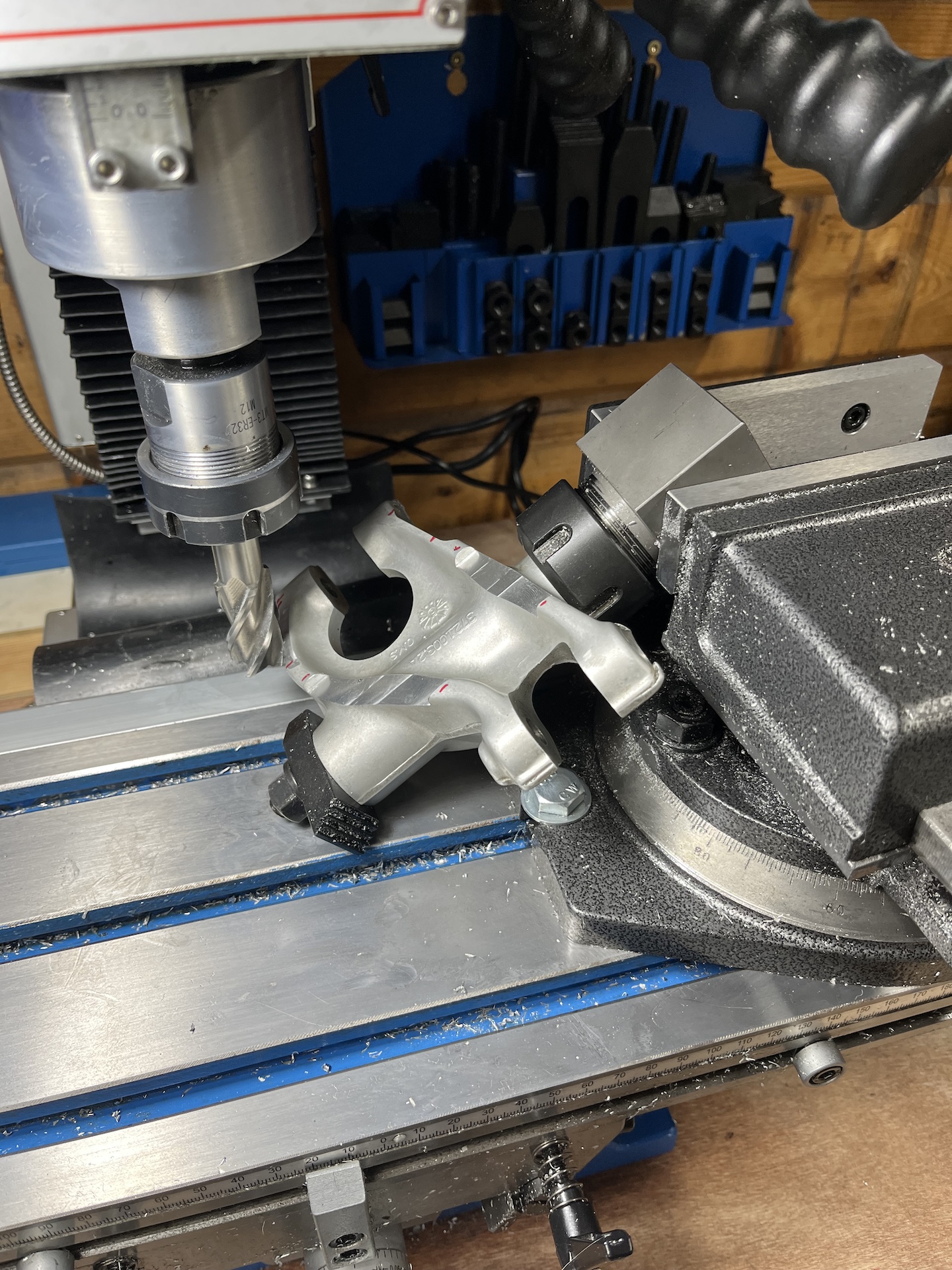
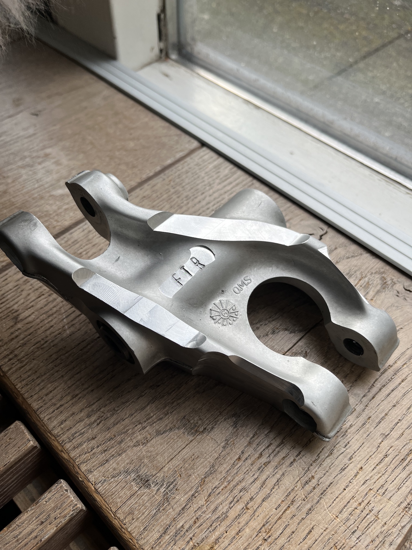
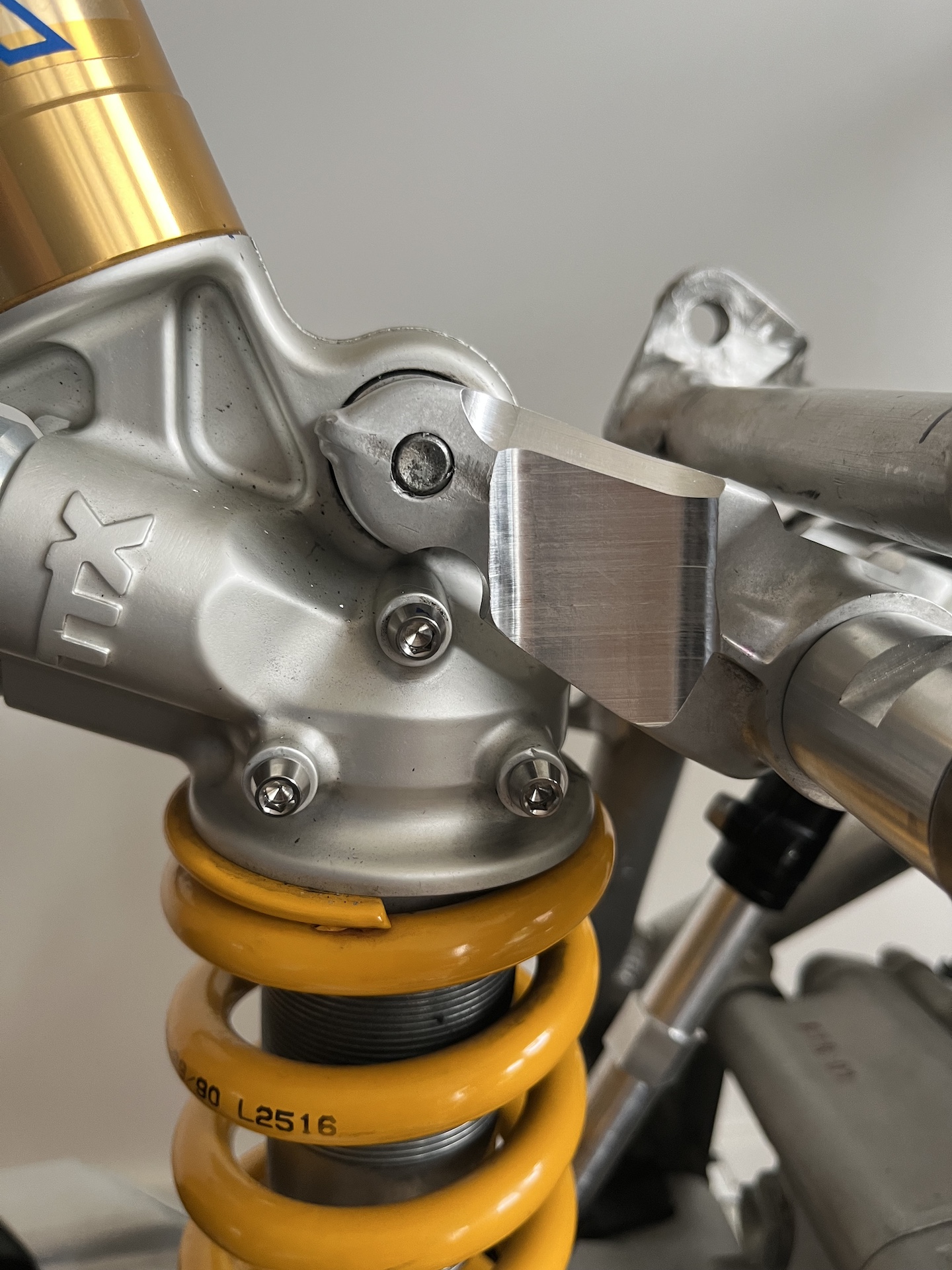
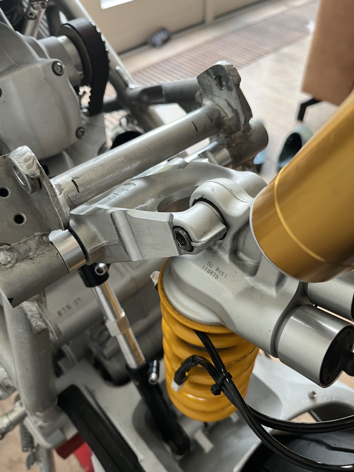
SUSPENSION ROCKER ARM MODIFICATIONS
Just some casual manual milling on a Friday. Needed some extra space for the exhaust heat shielding, so I milled down the sides of the rear shock rocker arm.
How I mounted the part on the mill can be considered questionable 😅……
I’m not worried about strength since this bike will be 50kg lighter than OEM and no option for a passenger.

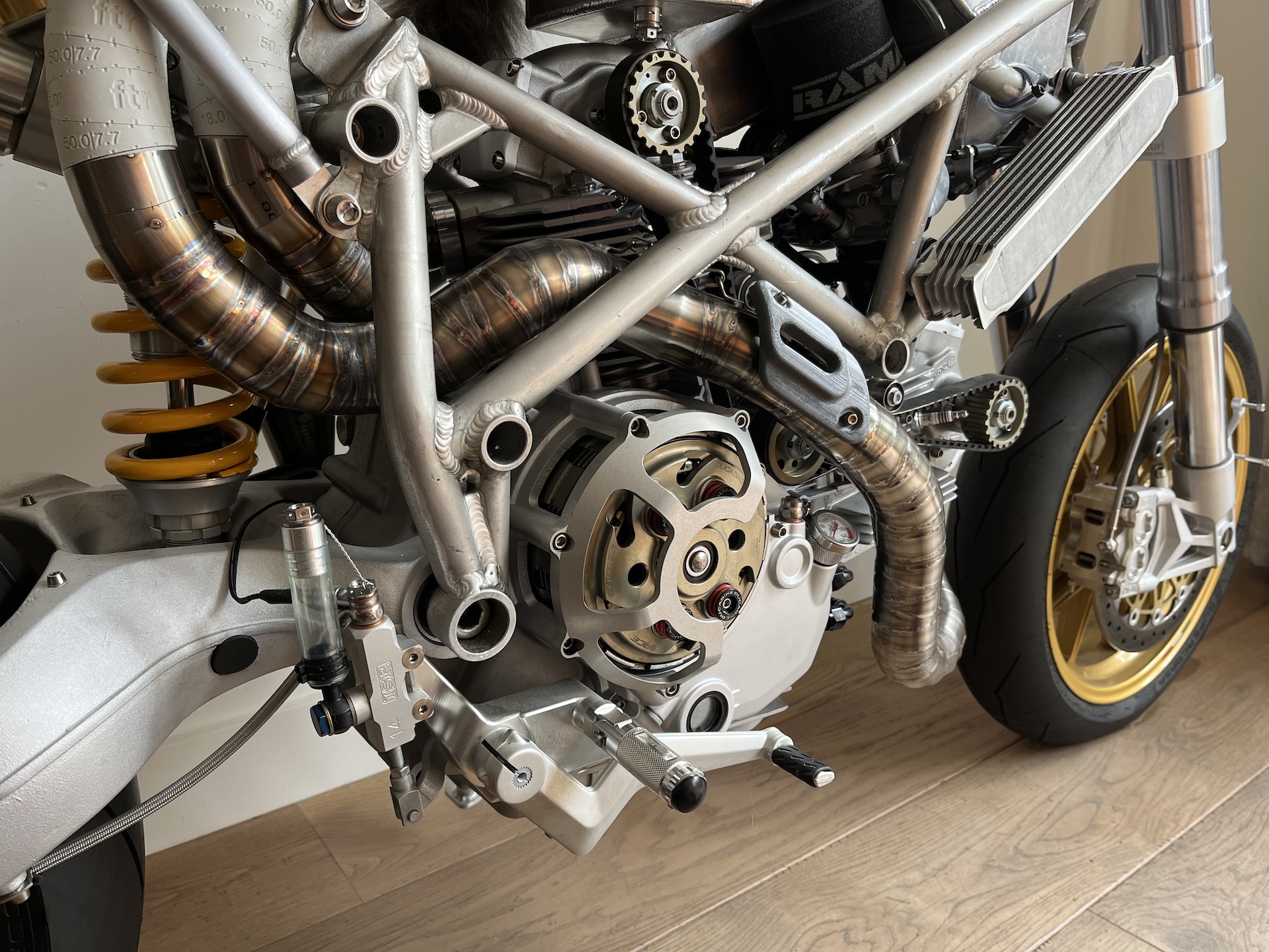
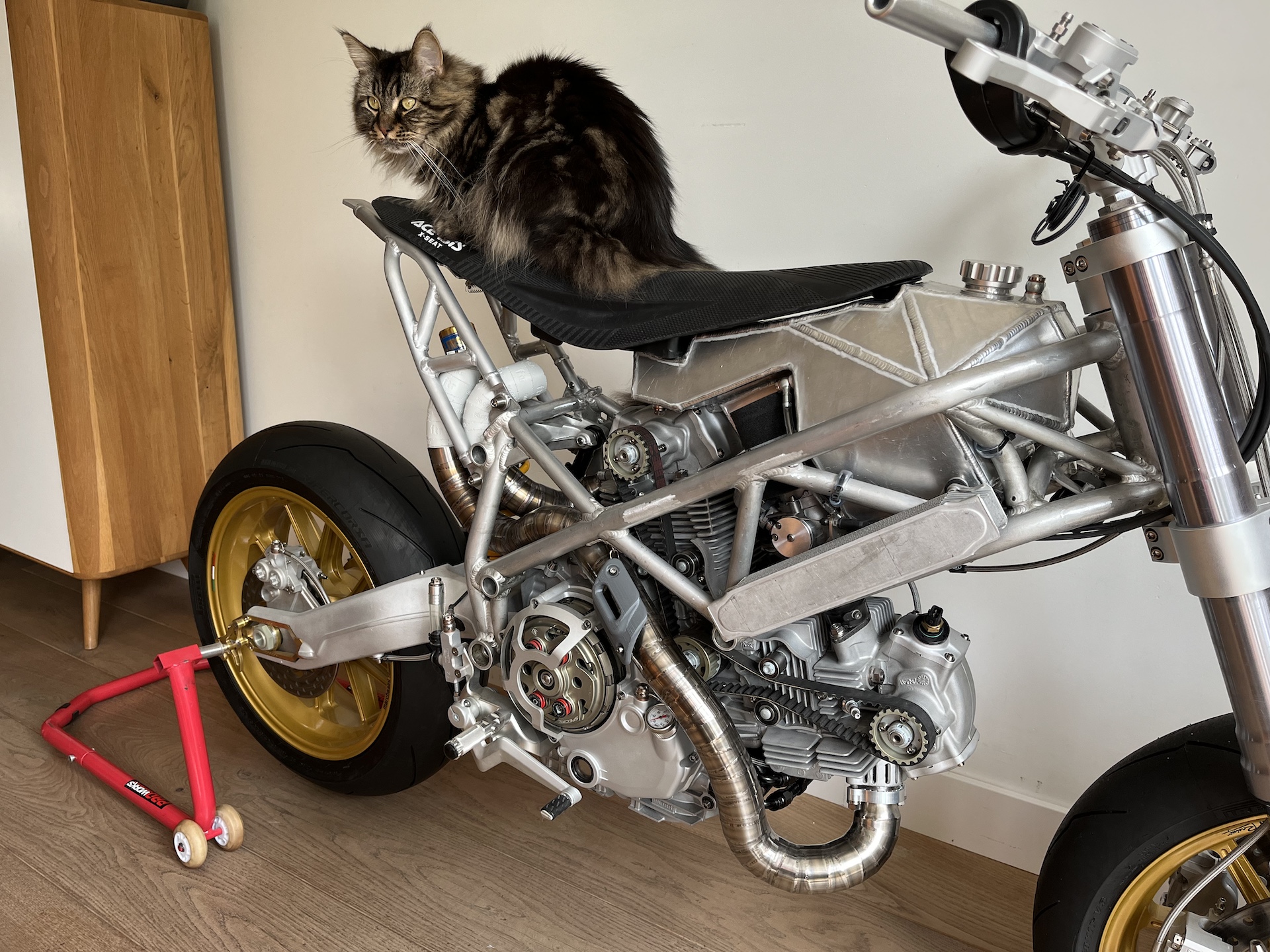
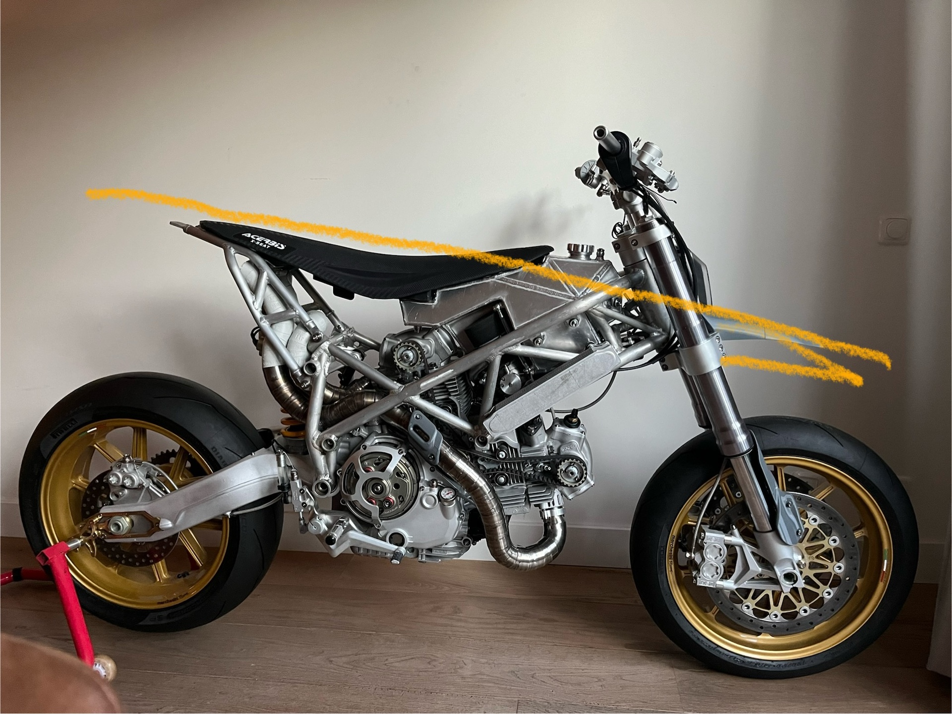
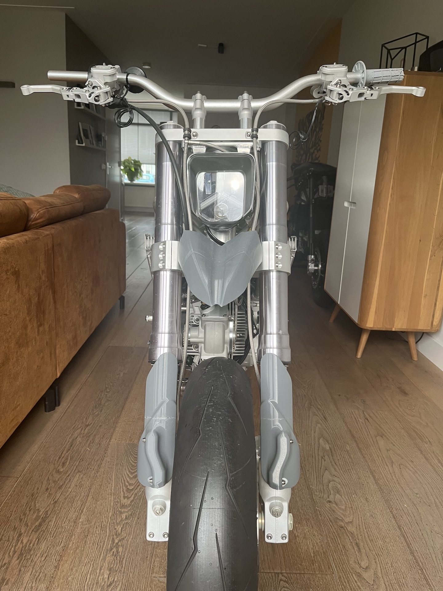
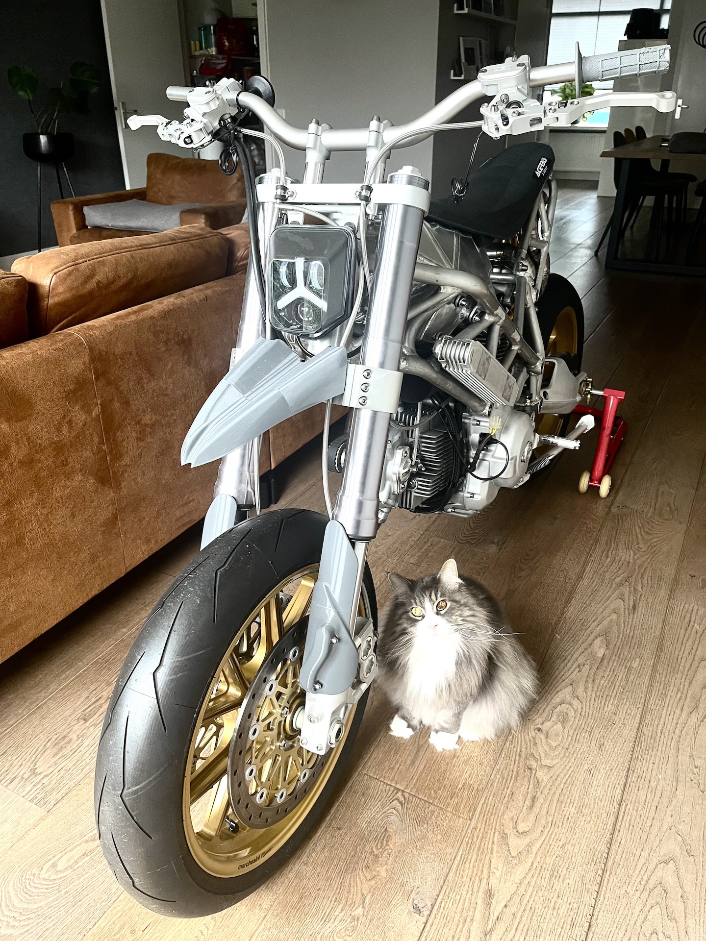
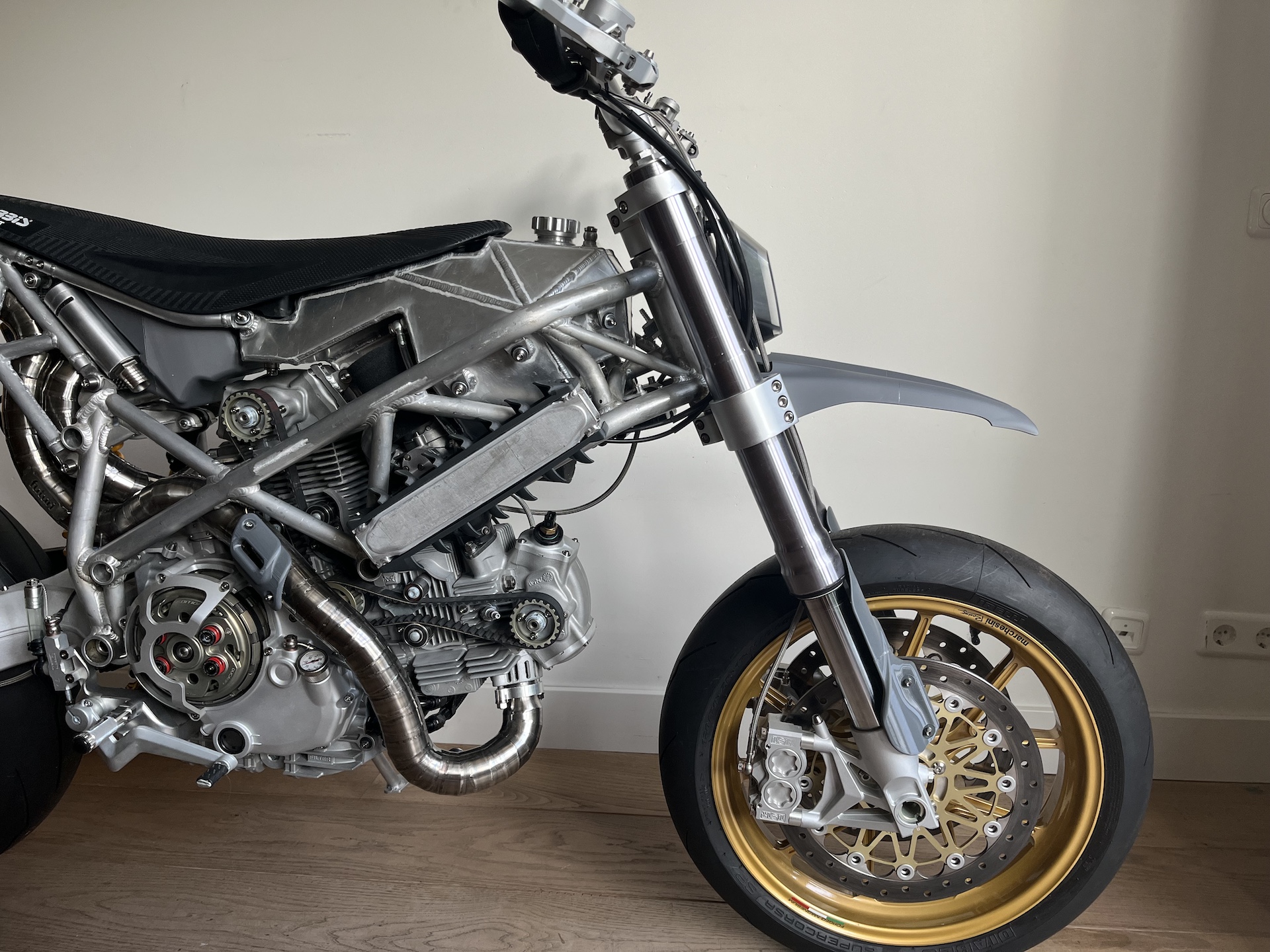
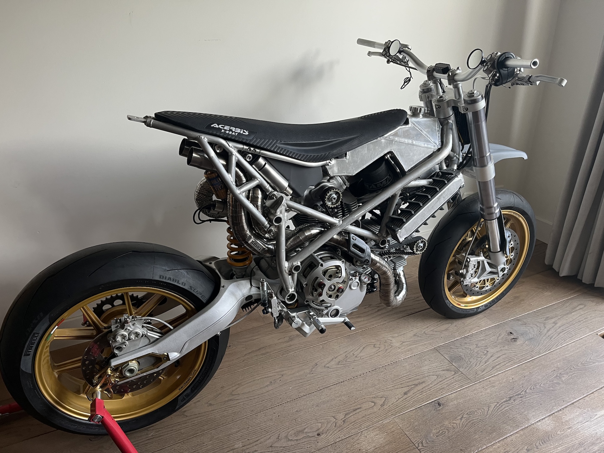
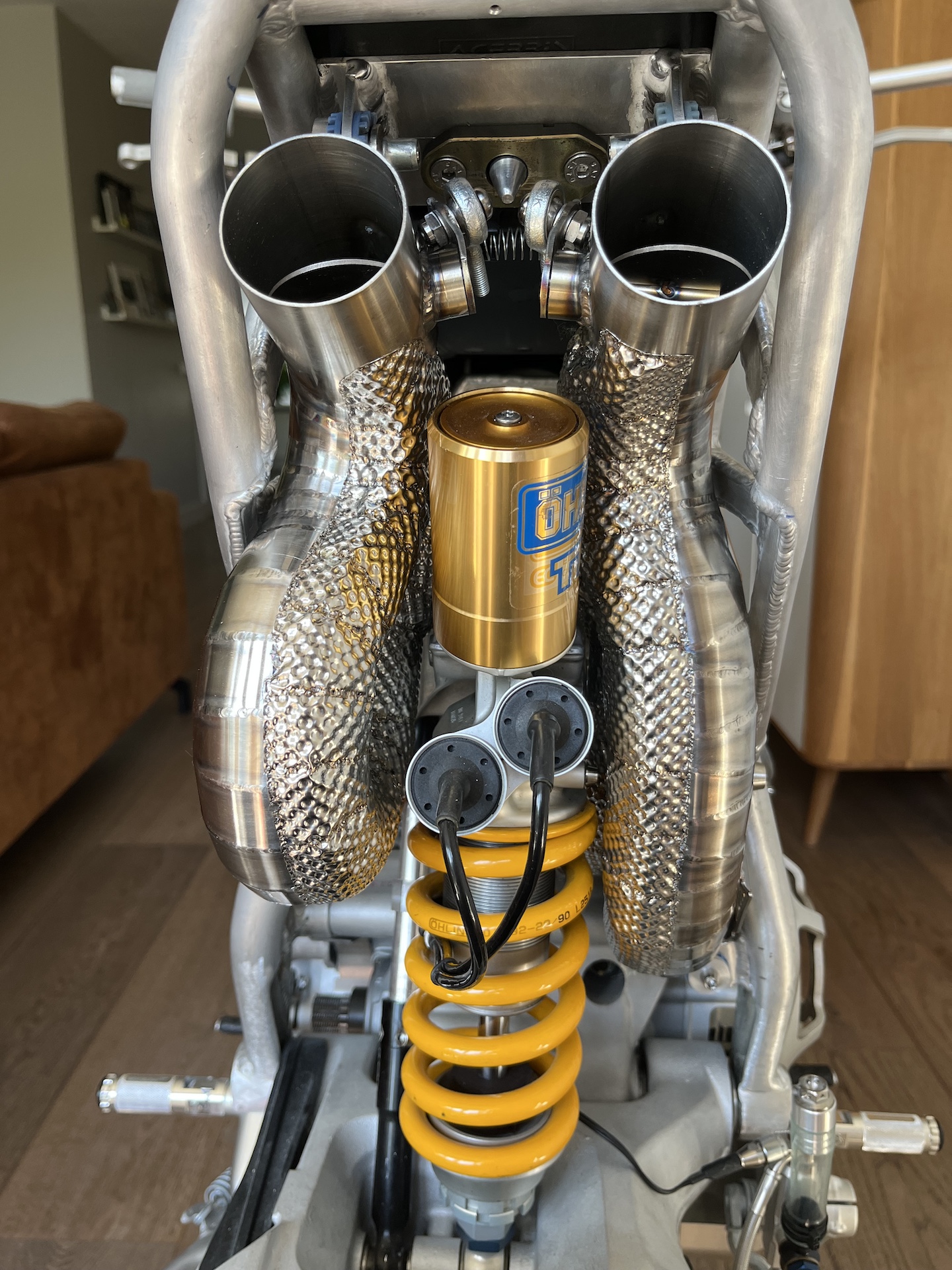
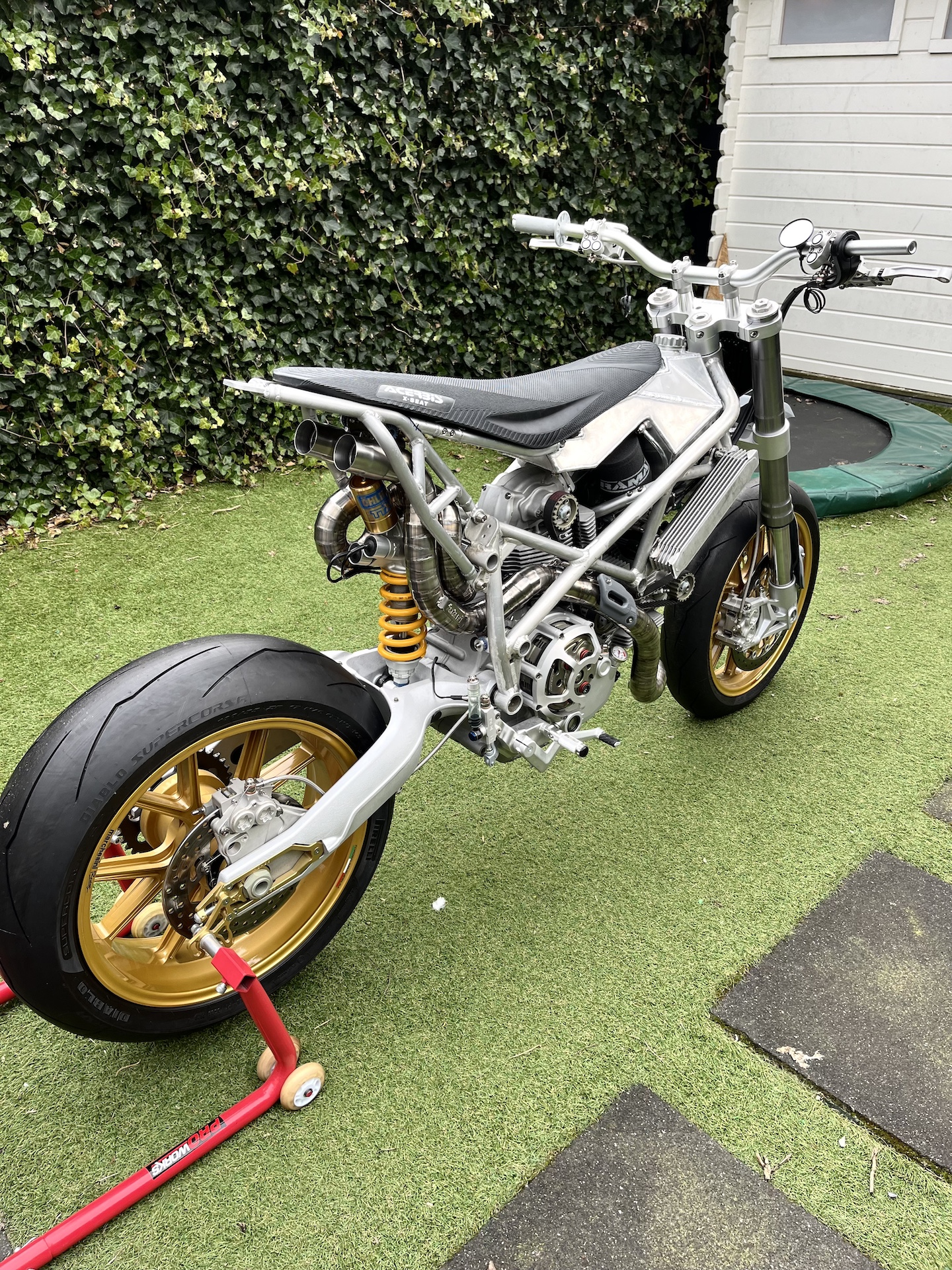
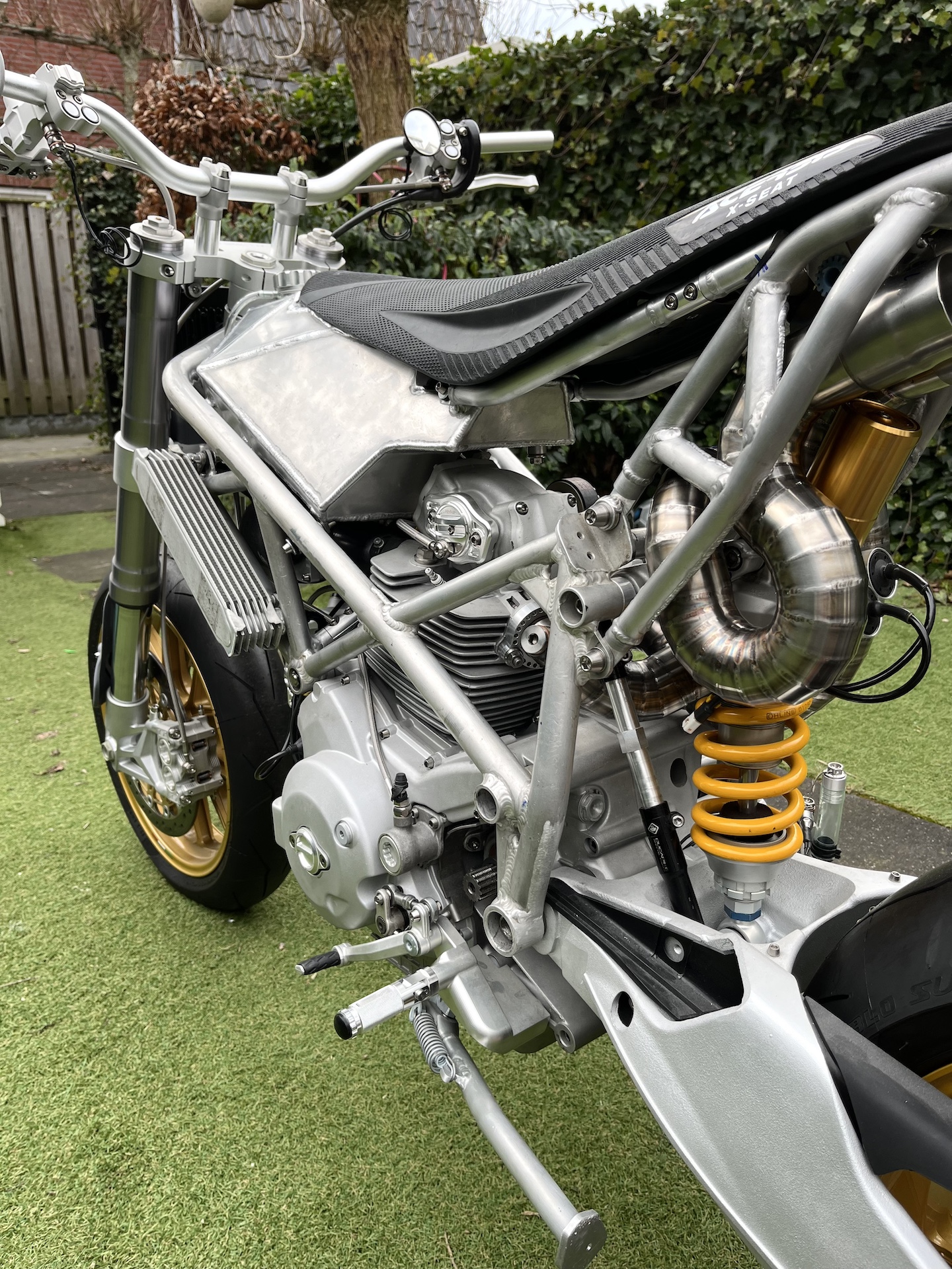
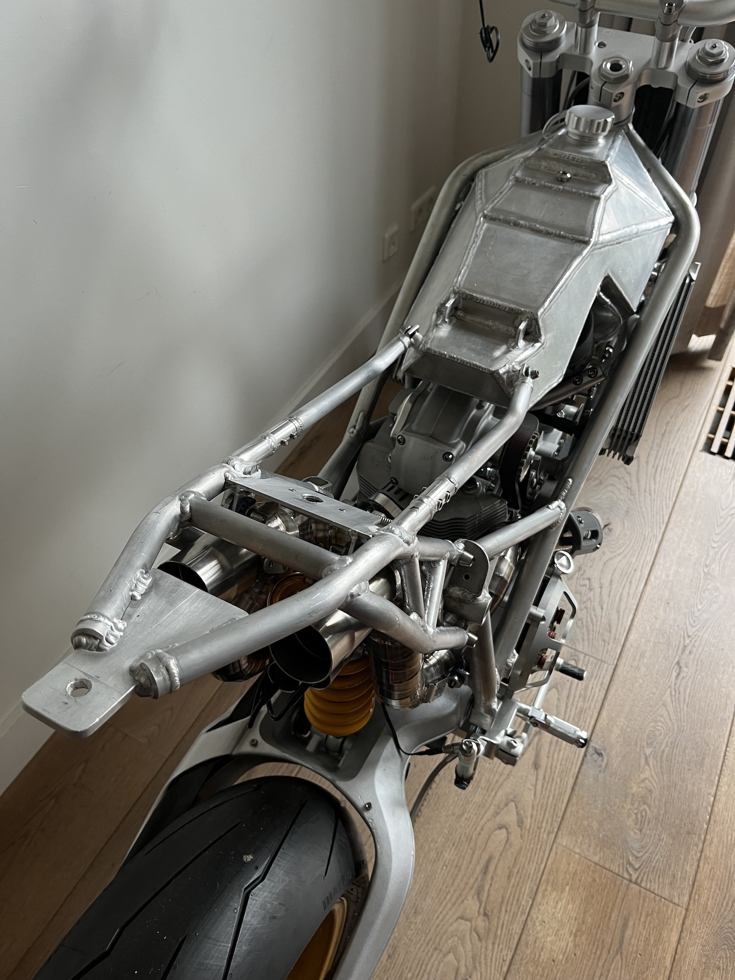
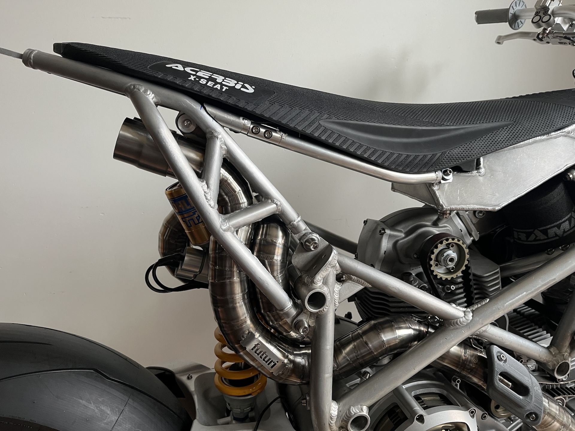
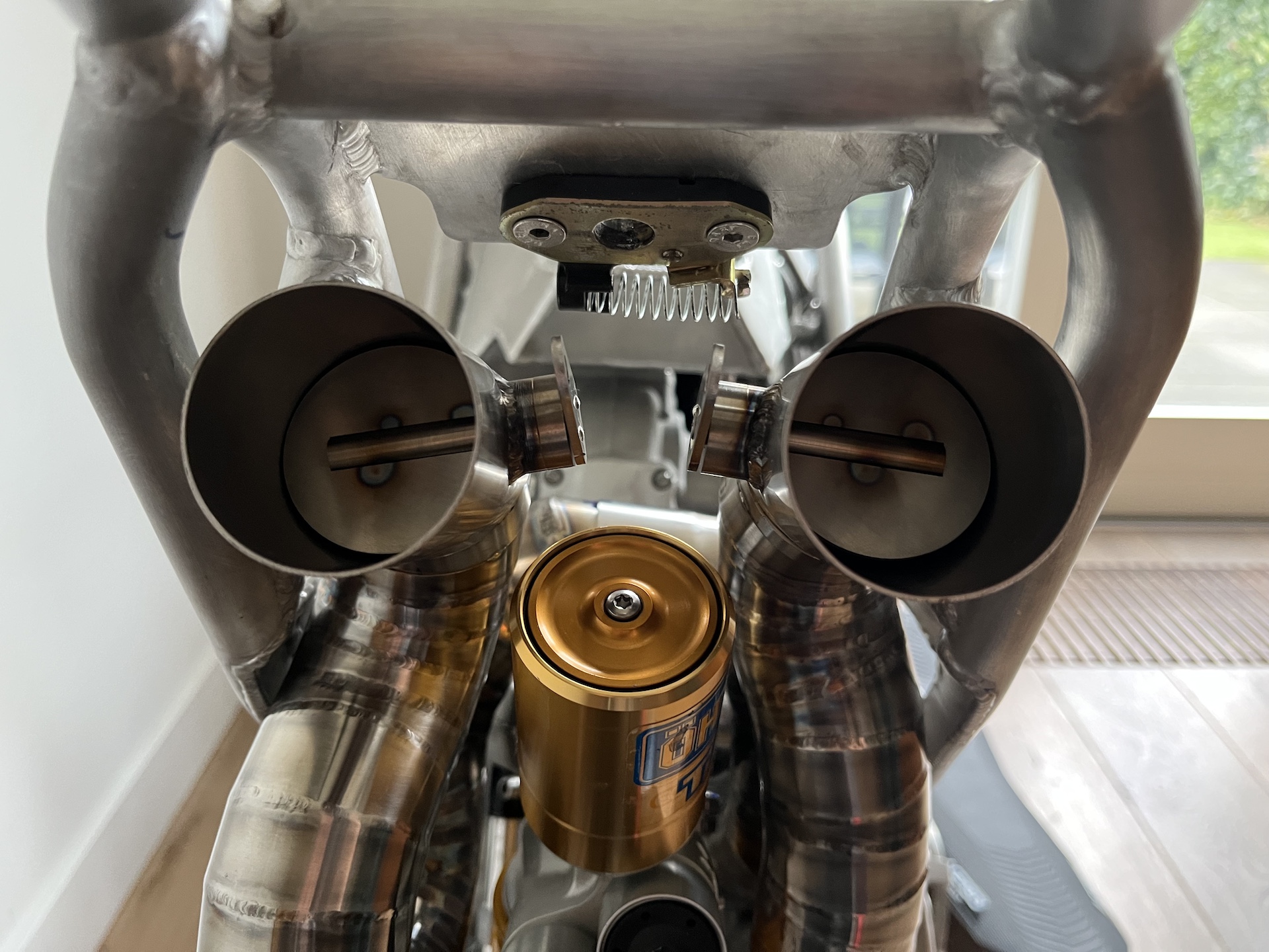
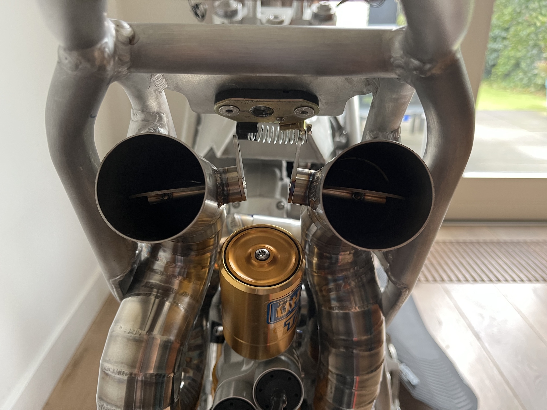
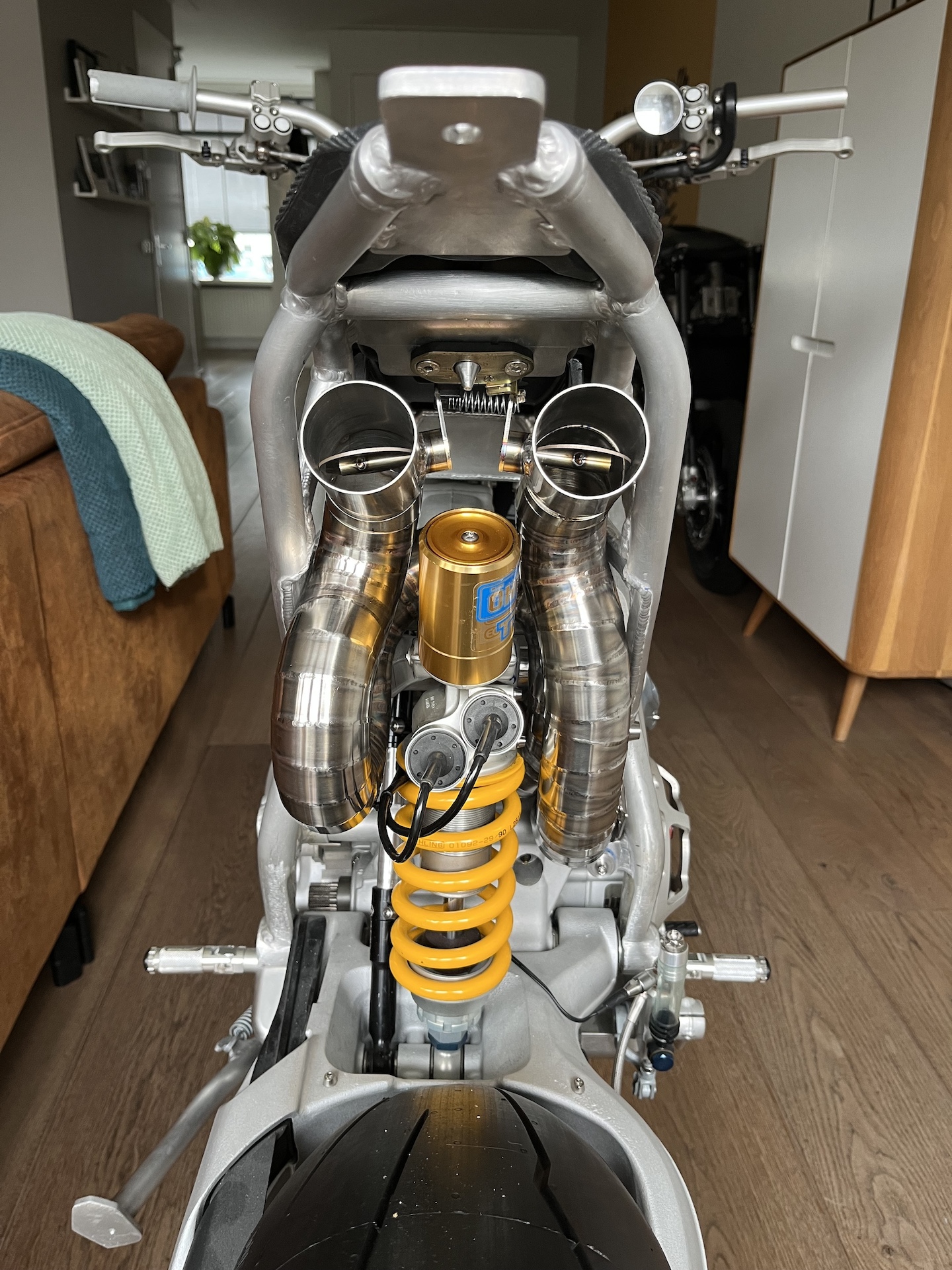
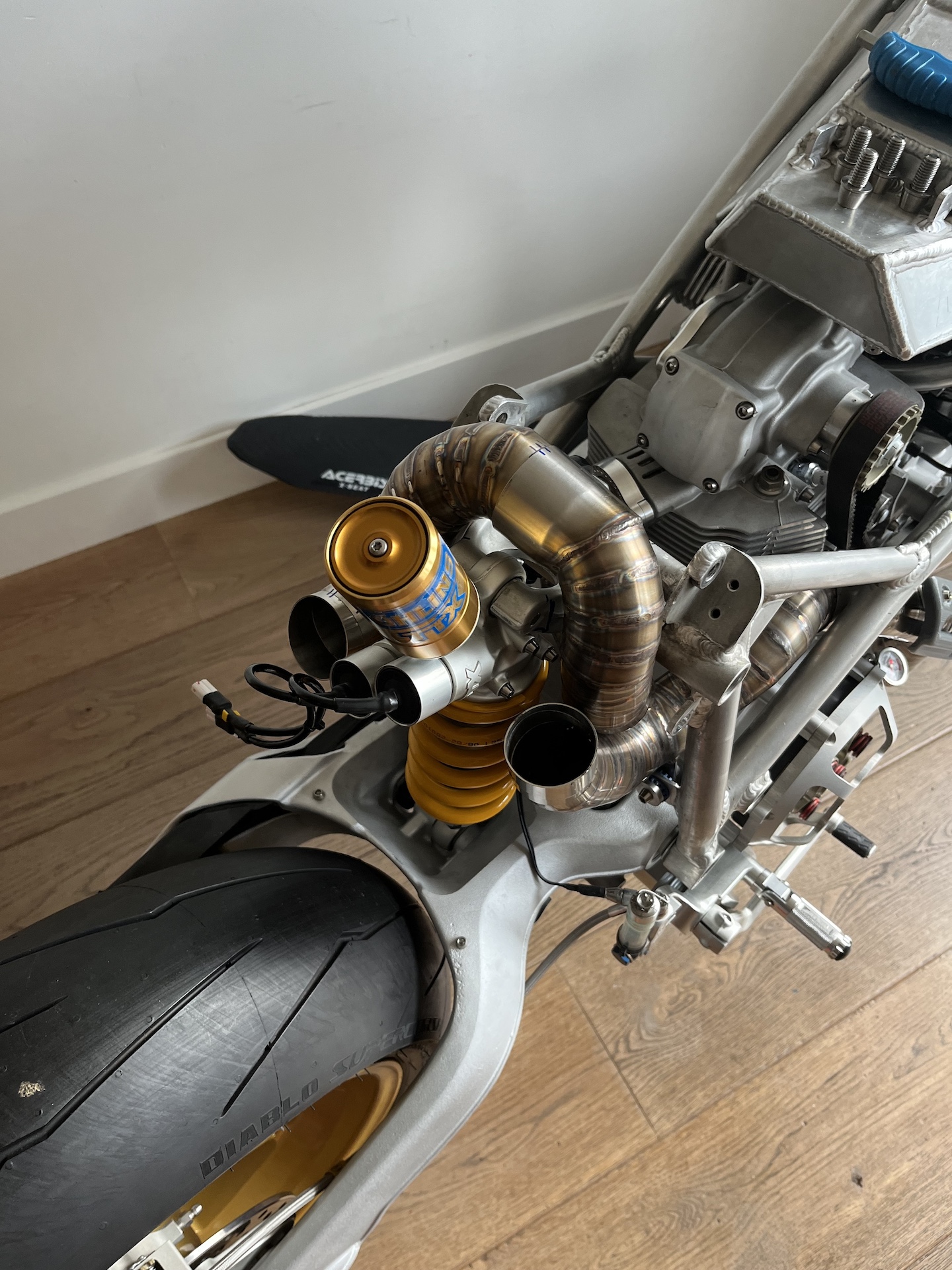
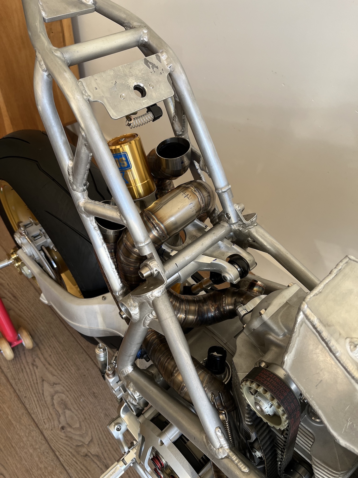
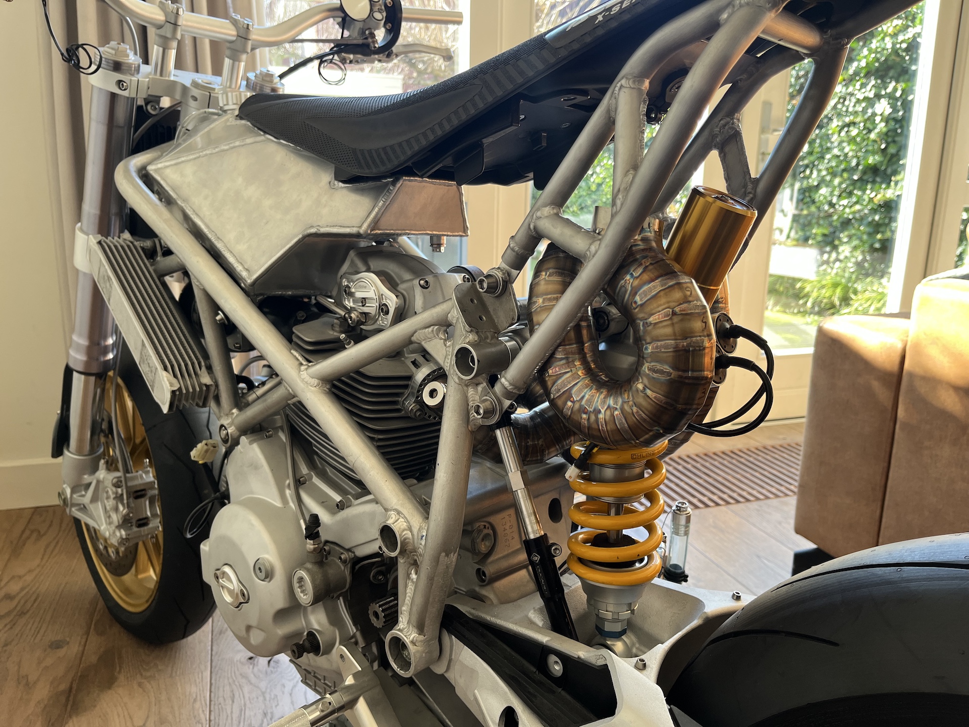
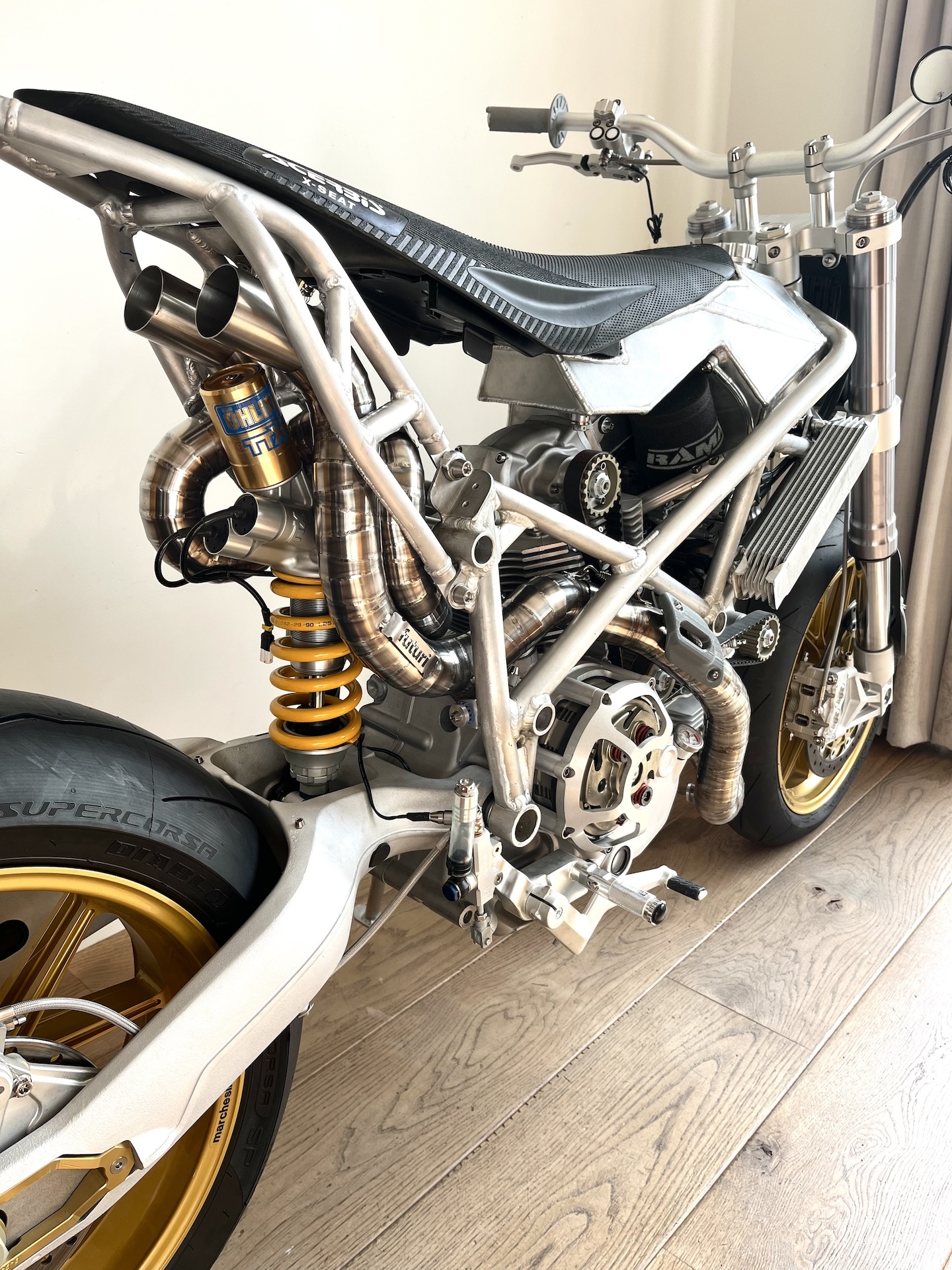
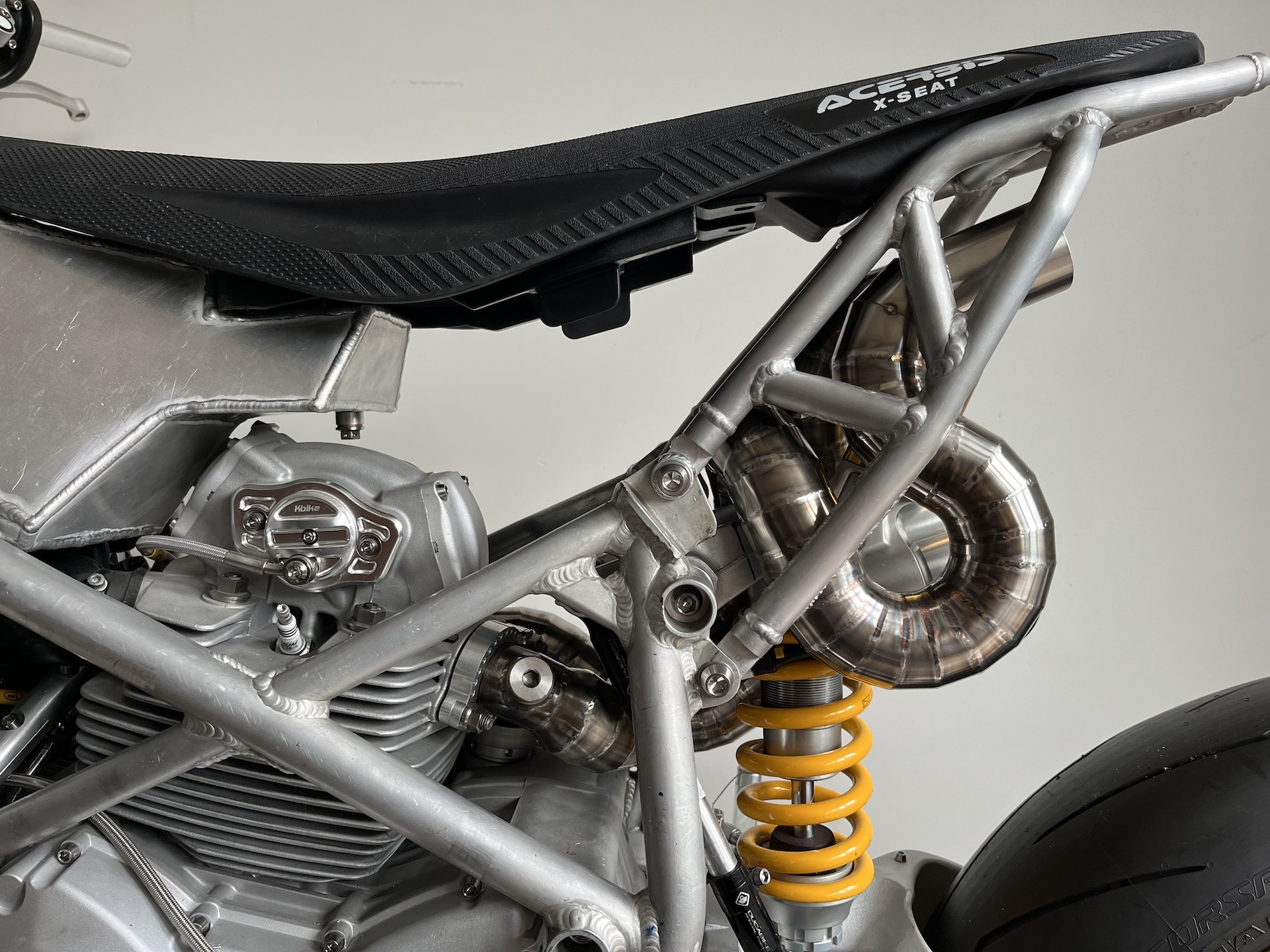
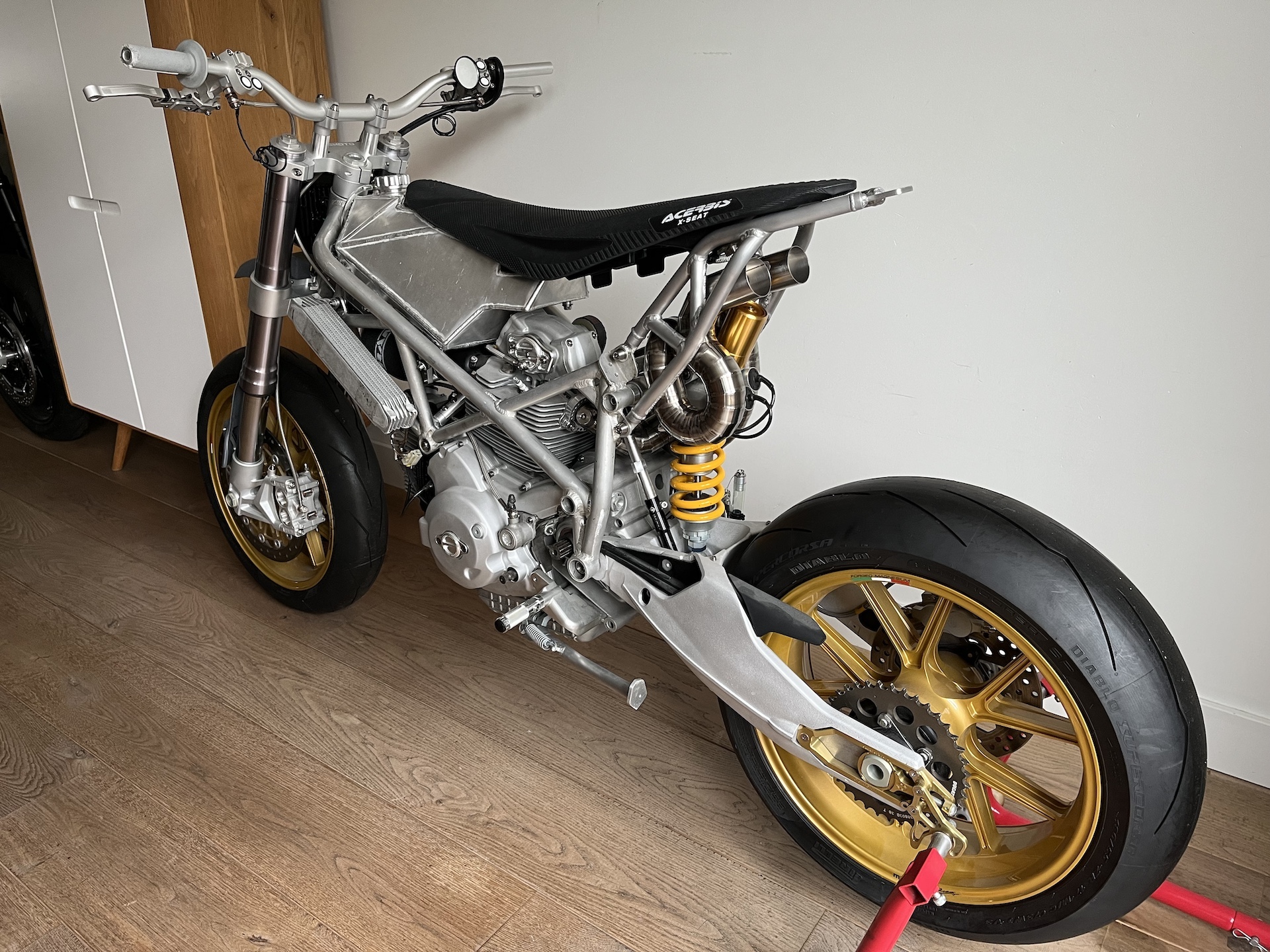
CURRENT STATE SNAPSHOT
The current snapshot state of Project Desmoto… Small changes here and there, and of course the latest largest progress on the exhaust system! It’s starting to look more and more finished by the week, but still in progress and allot of work todo…
To bad some of it will be covered by custom carbon fairings in the end.
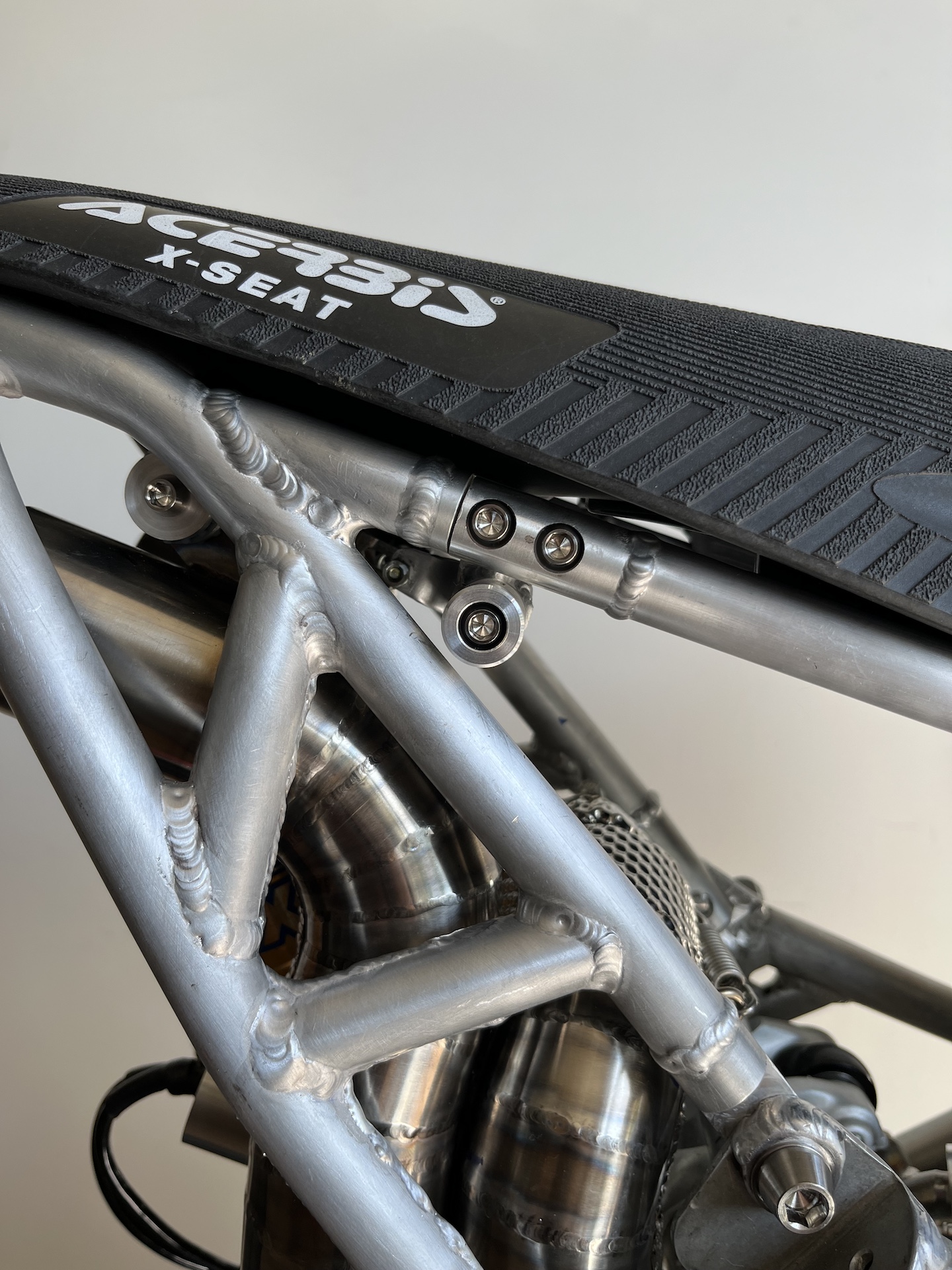
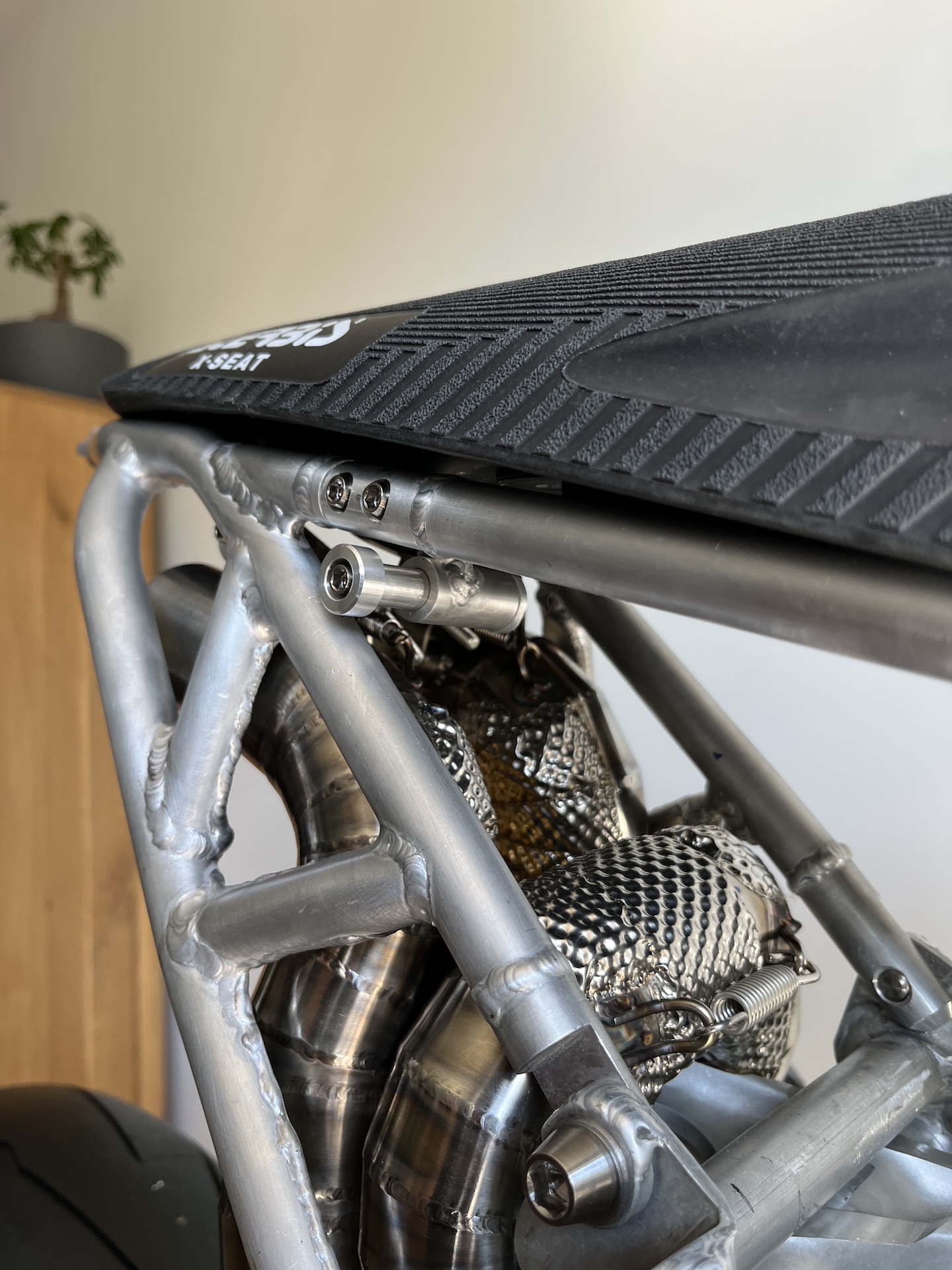
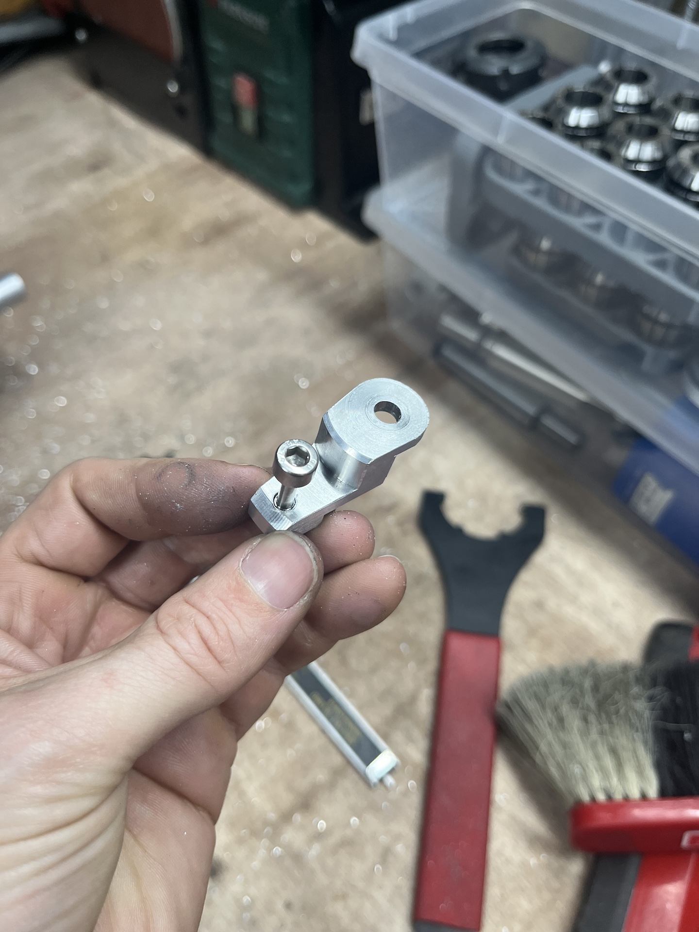
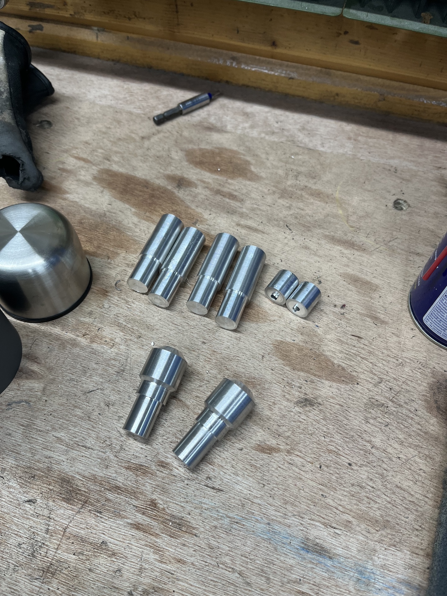
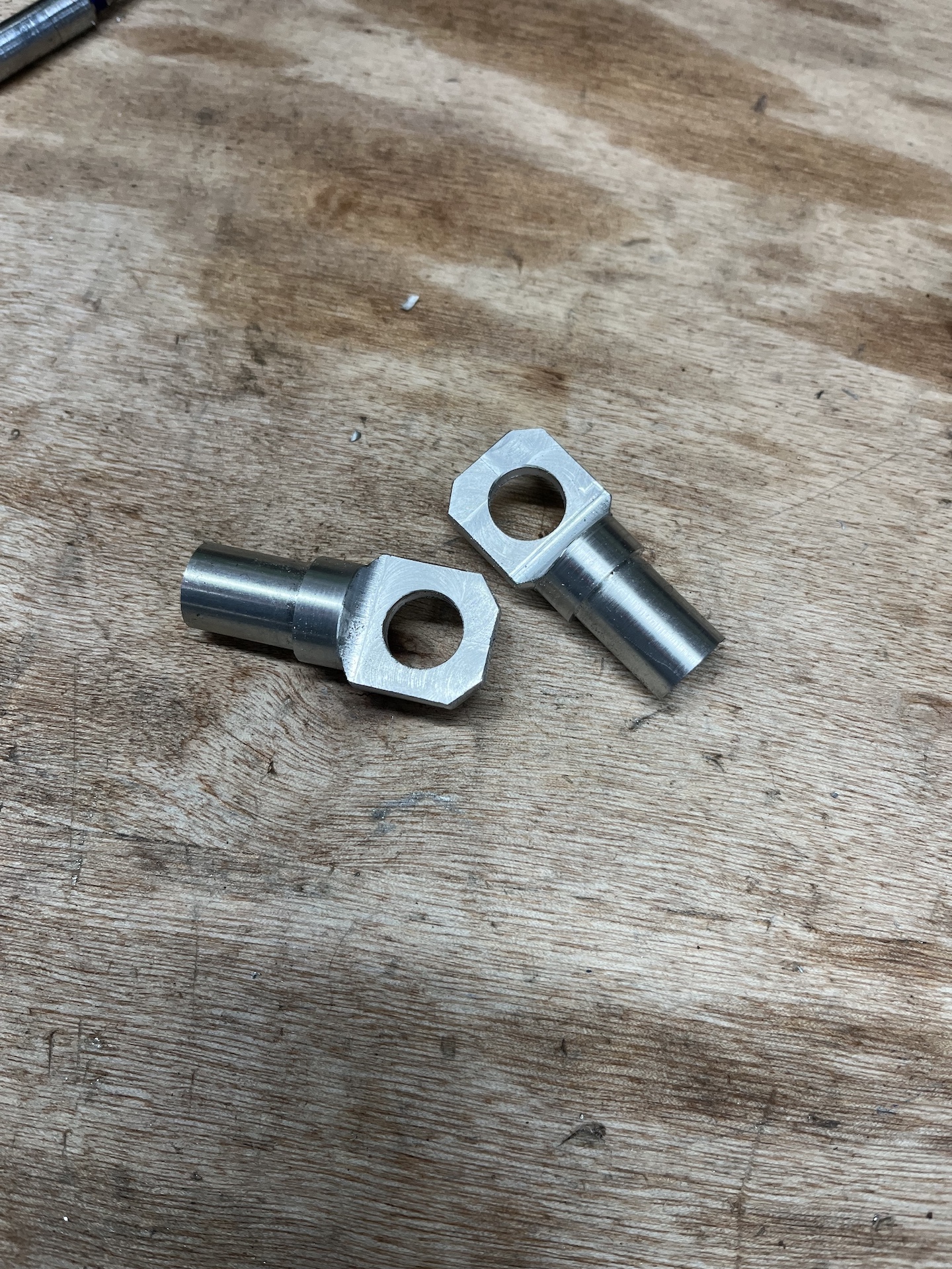
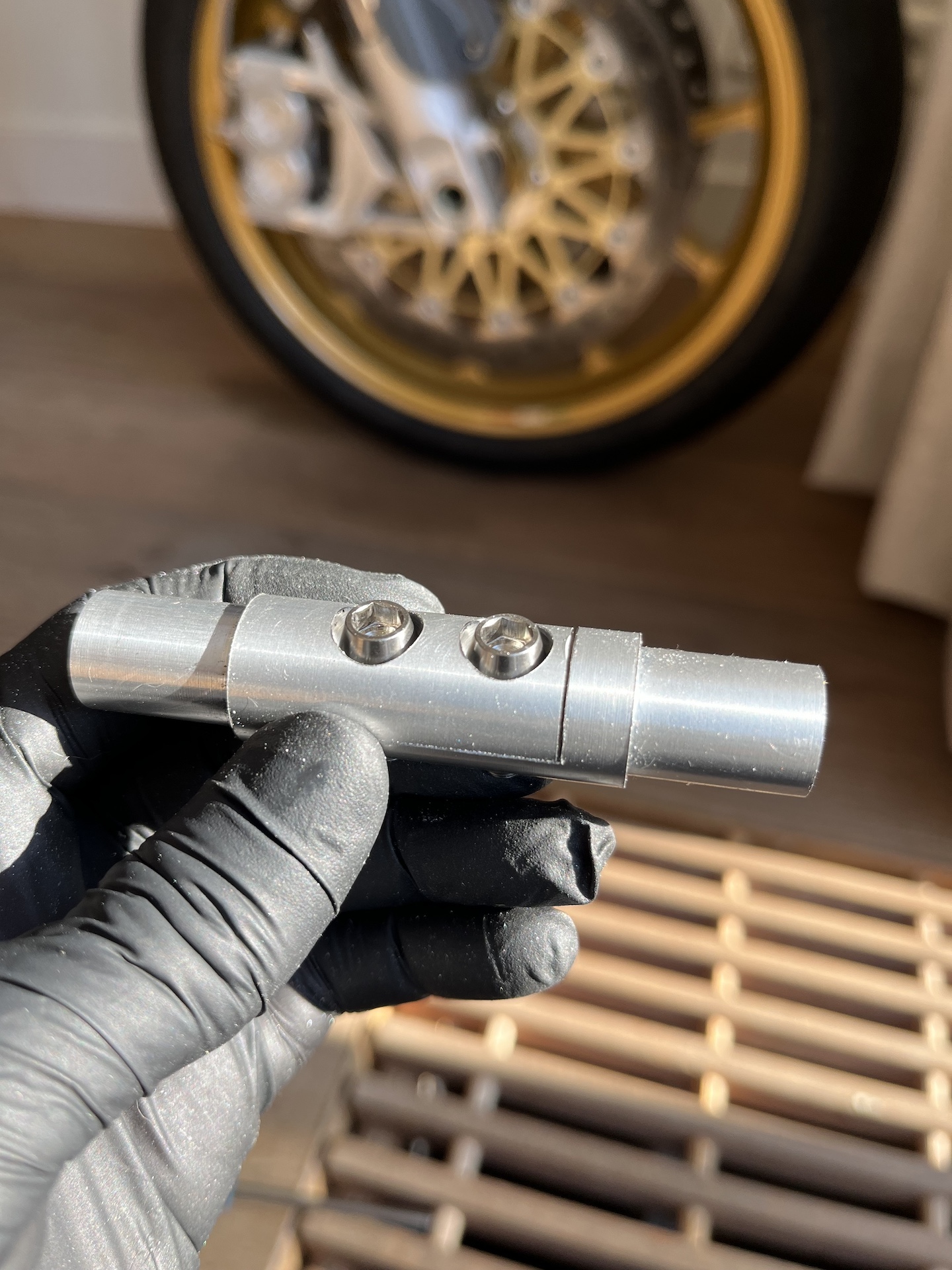
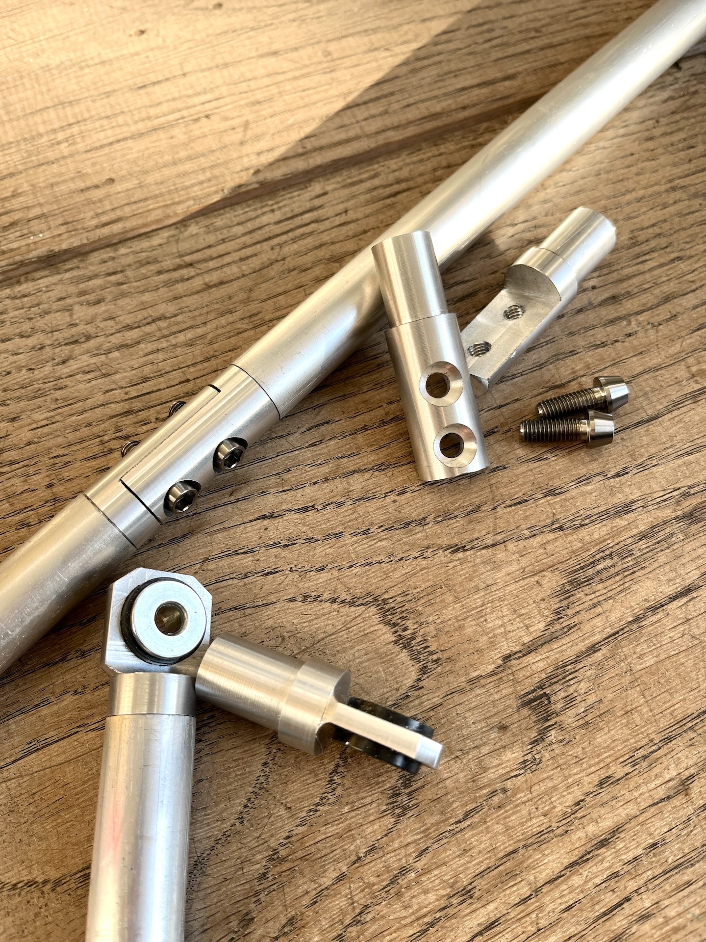
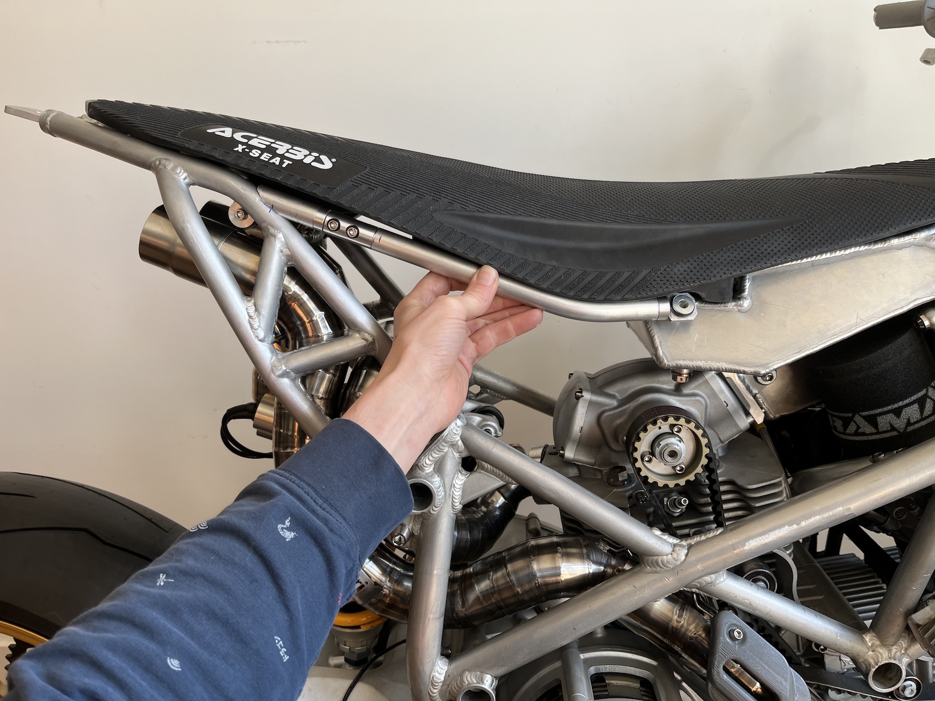
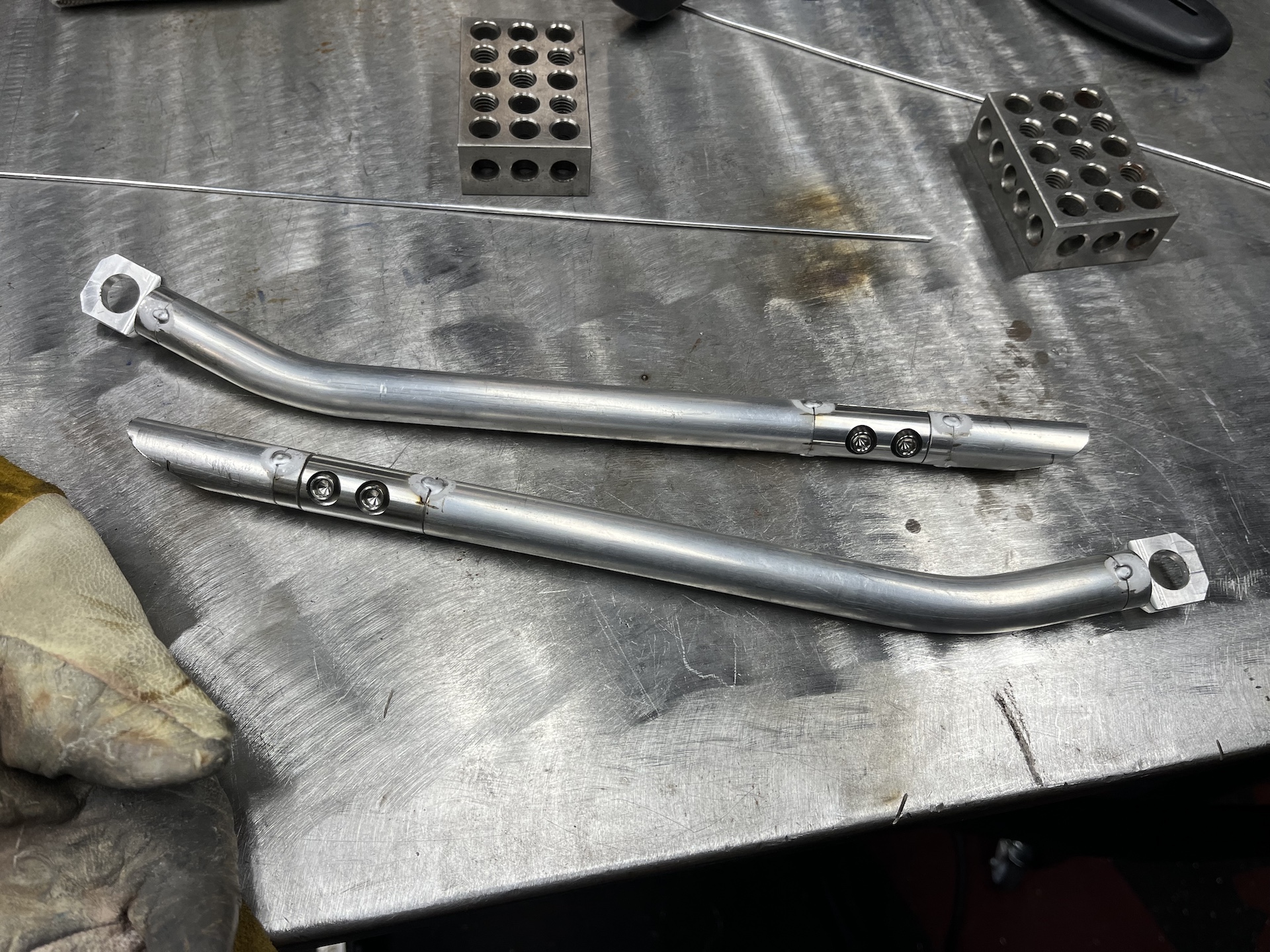
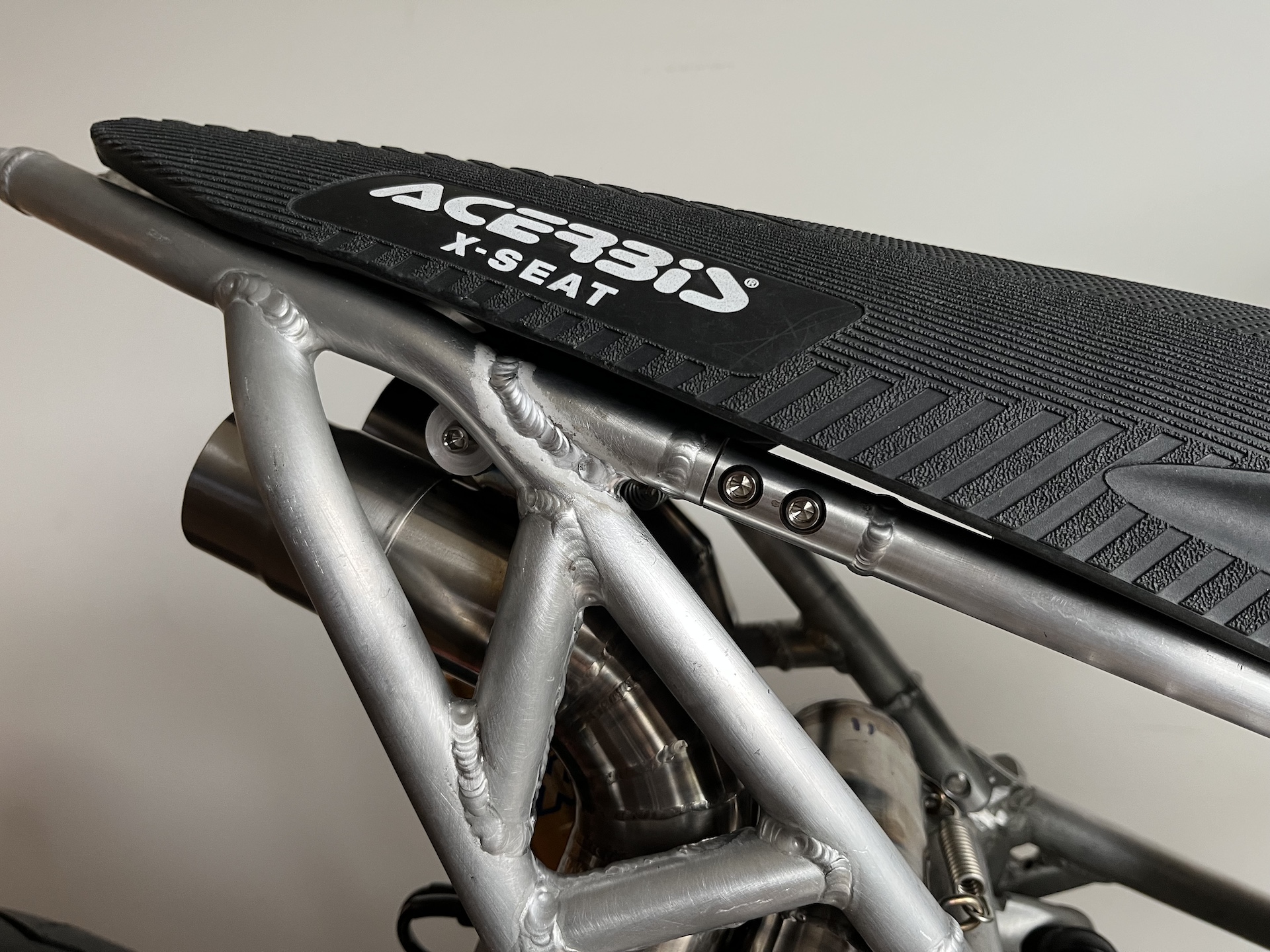
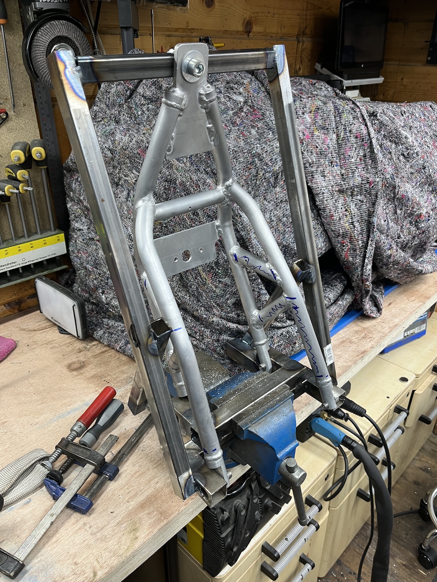
REMOVABLE SEAT BRACING
One of the items on the fabrication list was removable bracing where the seat would rest on. Now the seat just sags when you sit on it, so it needed some extra support to cary the weight of the rider.
A Saturday in the shed on the lathe and mill and the small parts are done. Will all be welded into 18mm OD tubing that has been bend in the correct shape.
Why removable? The subframe needs to be tilted up completely to be able to be removed. If these braces were not removable this rotation would not be possible :).
This is also the base/mount for the whole custom carbon electronics tray that will be mounted beneath the seat later on.
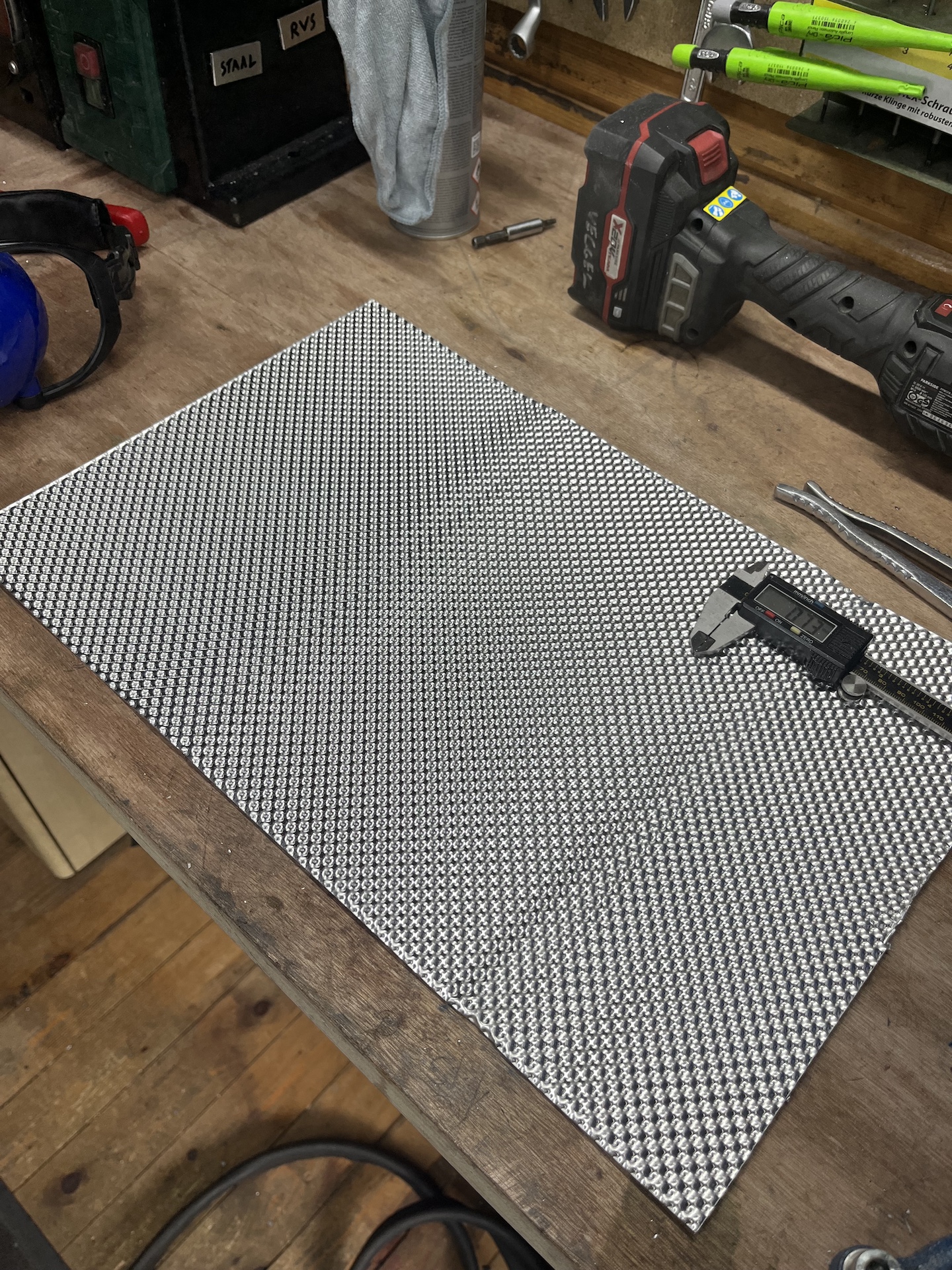
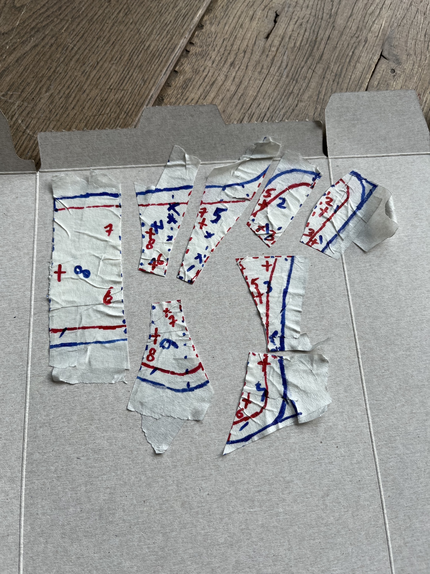
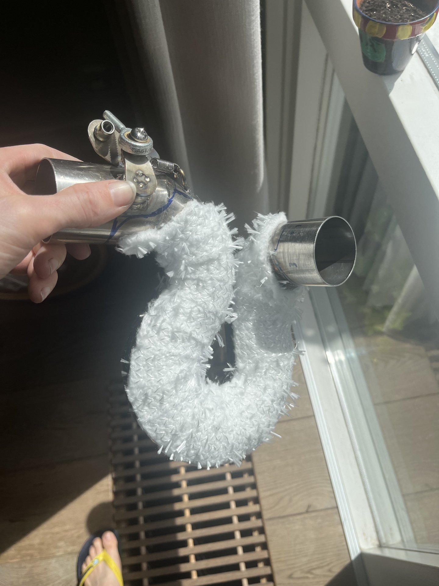
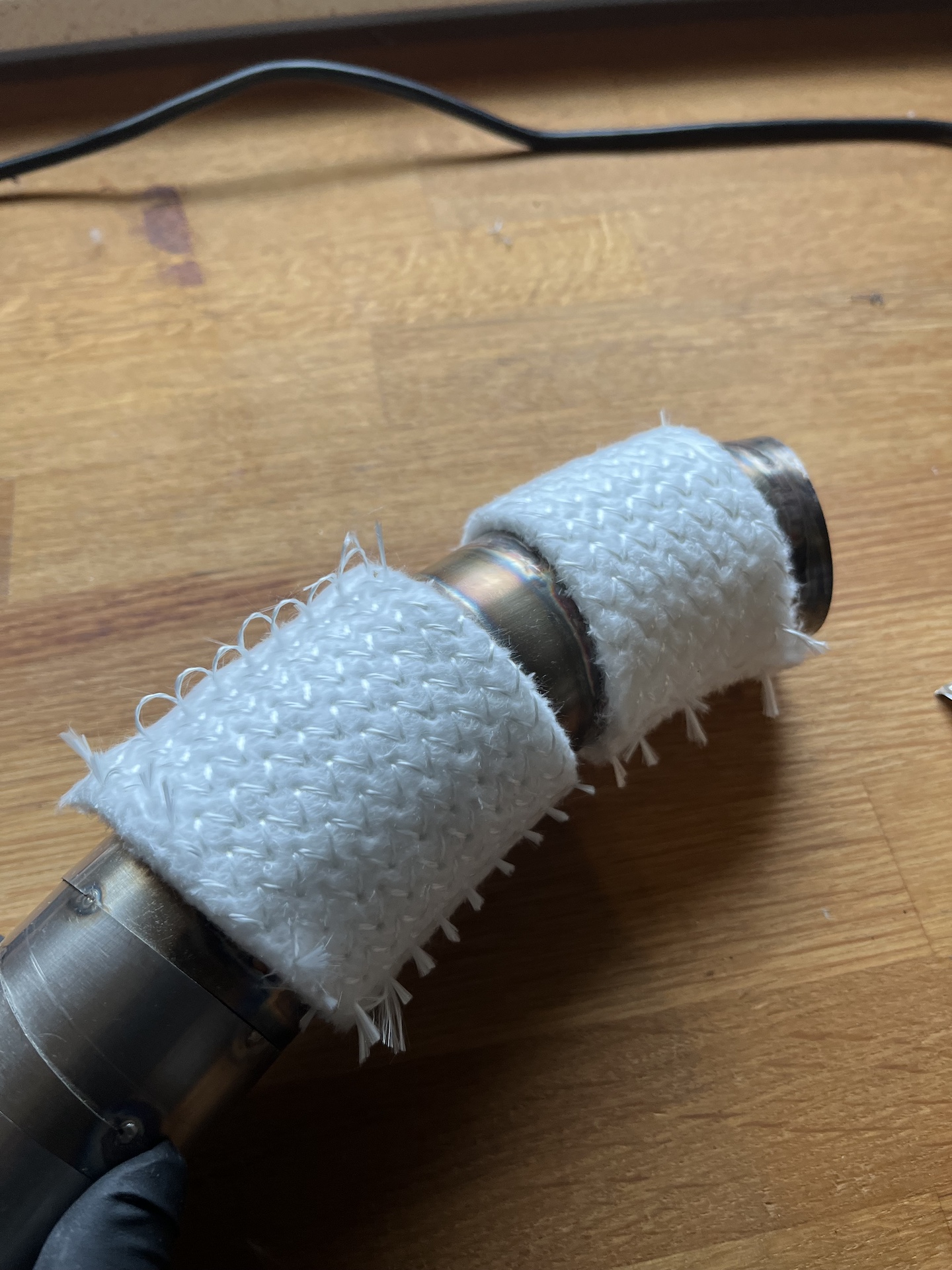
EXPERIMENTING WITH CUSTOM HEAT SHIELDING
Experimenting / testing the heat shielding solution I will be using on certain parts on the exhaust of project Desmoto. I know this is not completely realistic but it shows the rough potential!
I did multiple tests and got a large part of the exhaust glowing red hot (600 to 800C) (not on this video, that wasn’t safe 😂), and the shielding surface temperature was only rising to 100C. I had no problem holding my hand super close to the shielding. Almost NO radiation heat!
Looks really promising, and I am pretty sure this will work perfectly to preserve my rear shock!
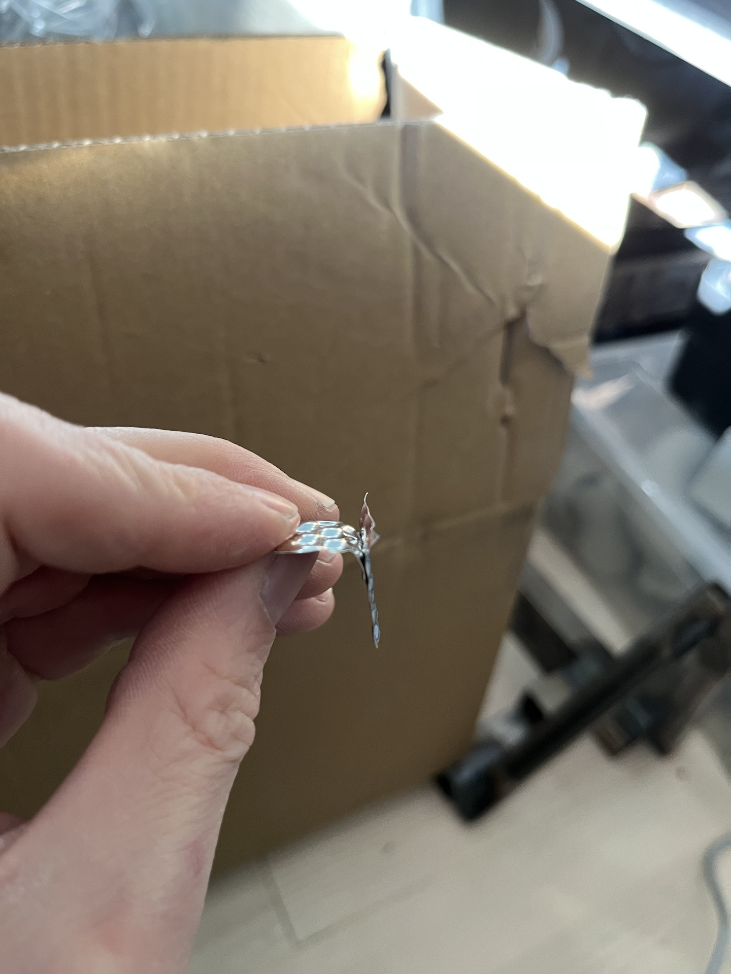
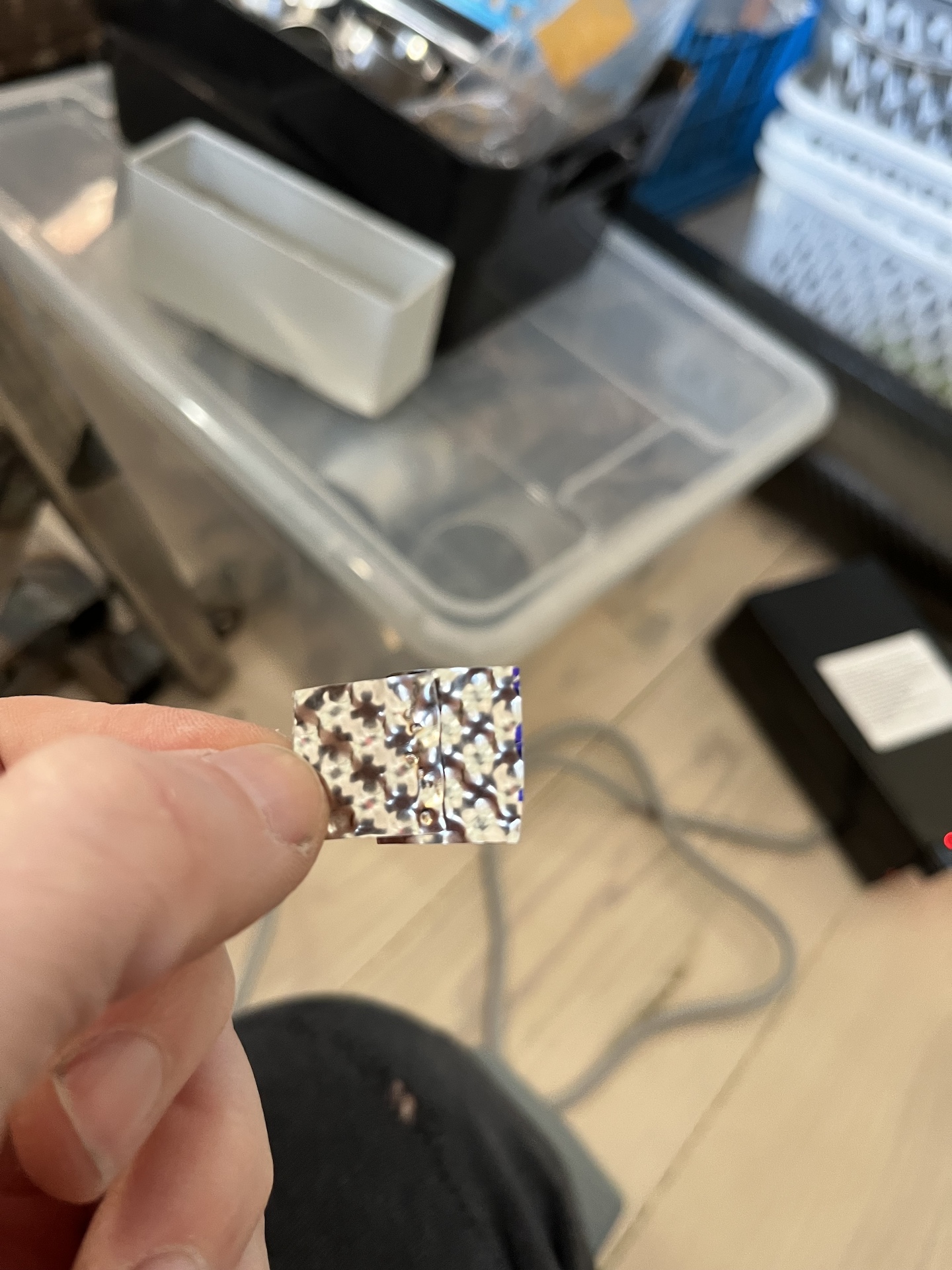
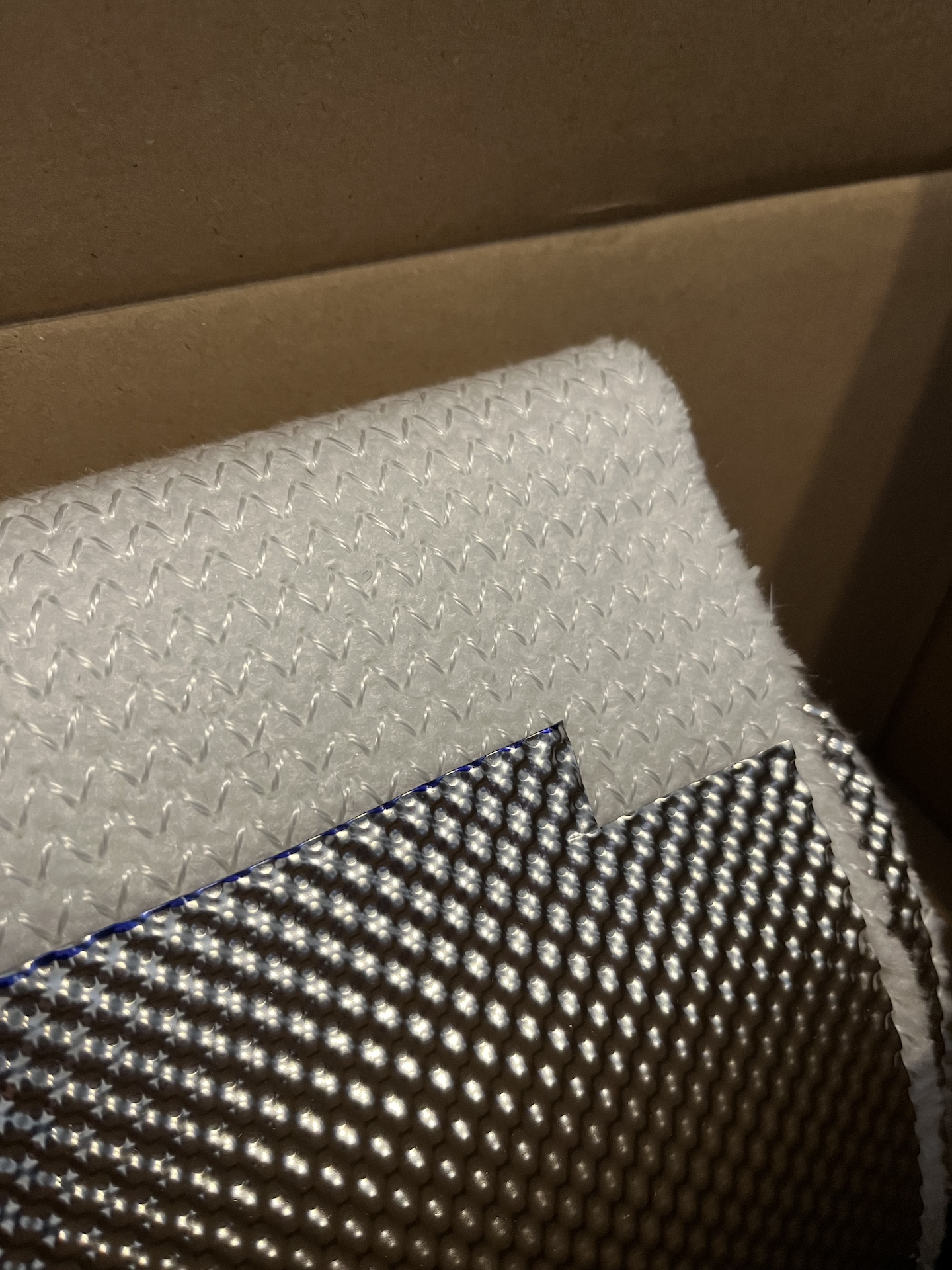
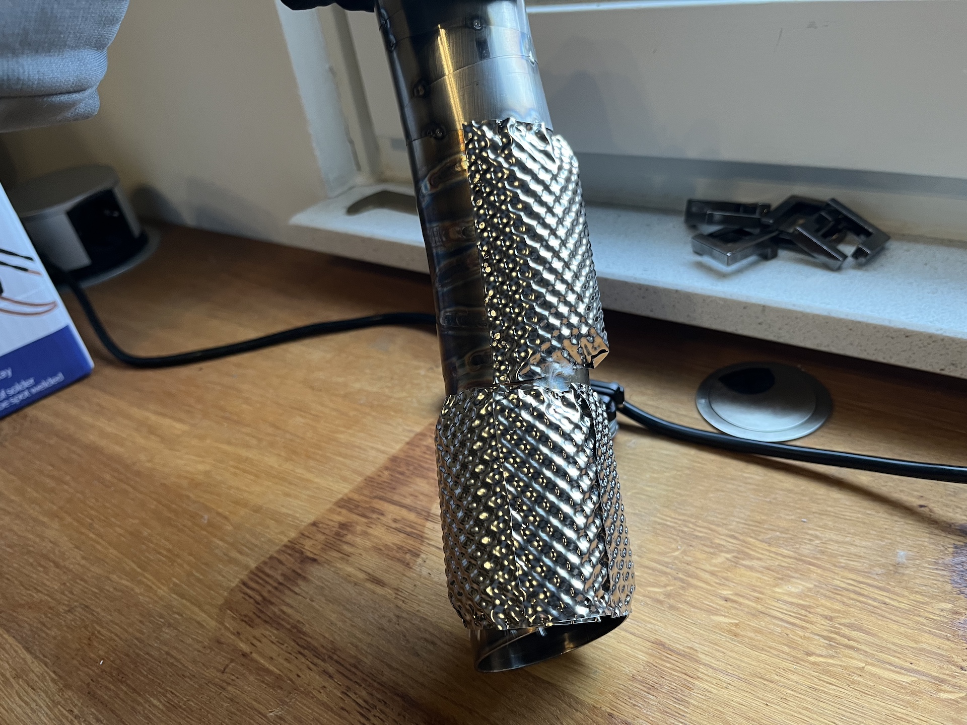
This method is also used on professional race cars manifolds and turbos. Wrapping with ceramic wool (1000C resistant) and covering that with 0.1mm embossed stainless steel sheeting mounted using spot welds.
This method should reduce surface exhaust heat by 50% and radiation heat by 90%. In this test it seems to perform even better!


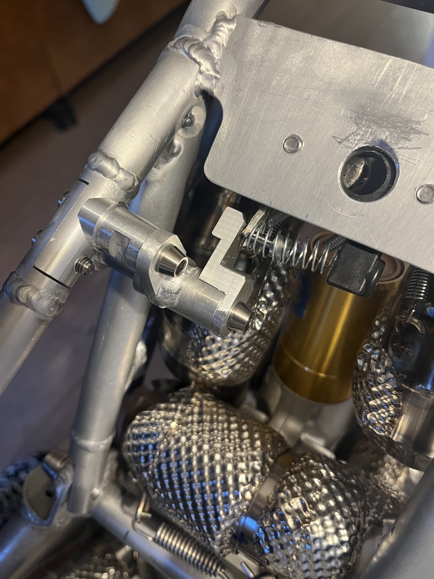
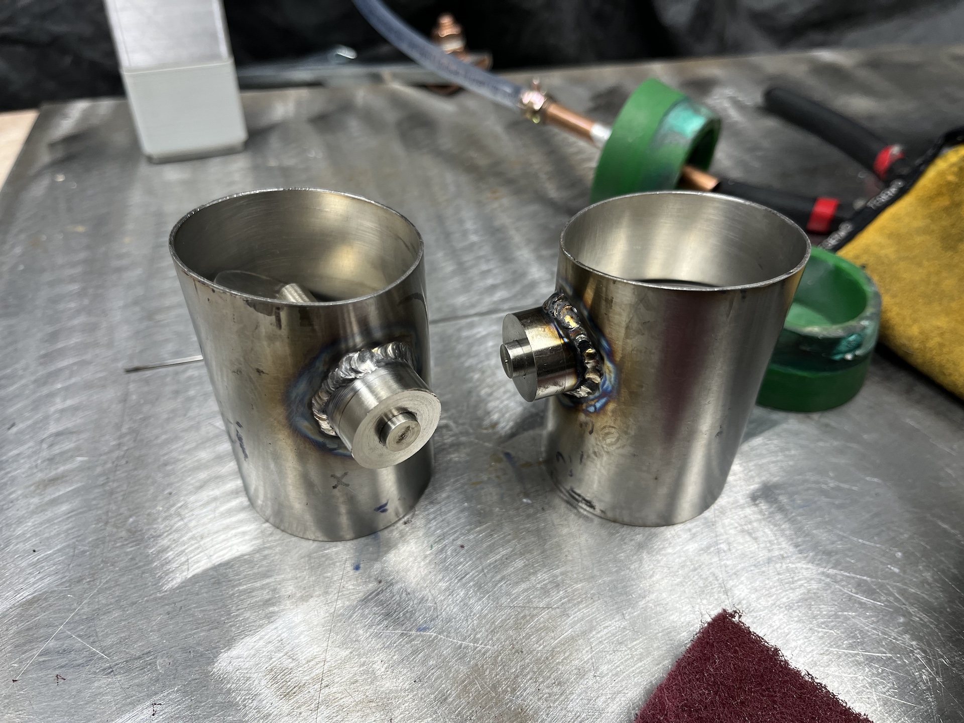
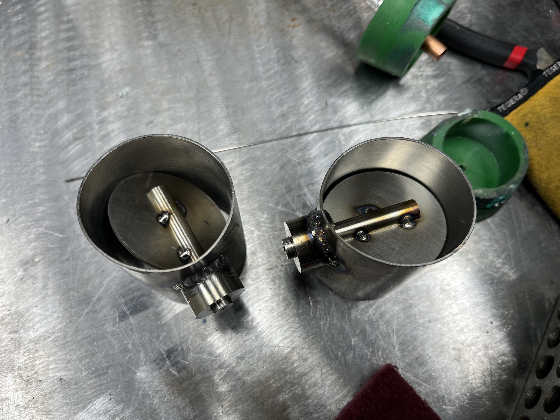
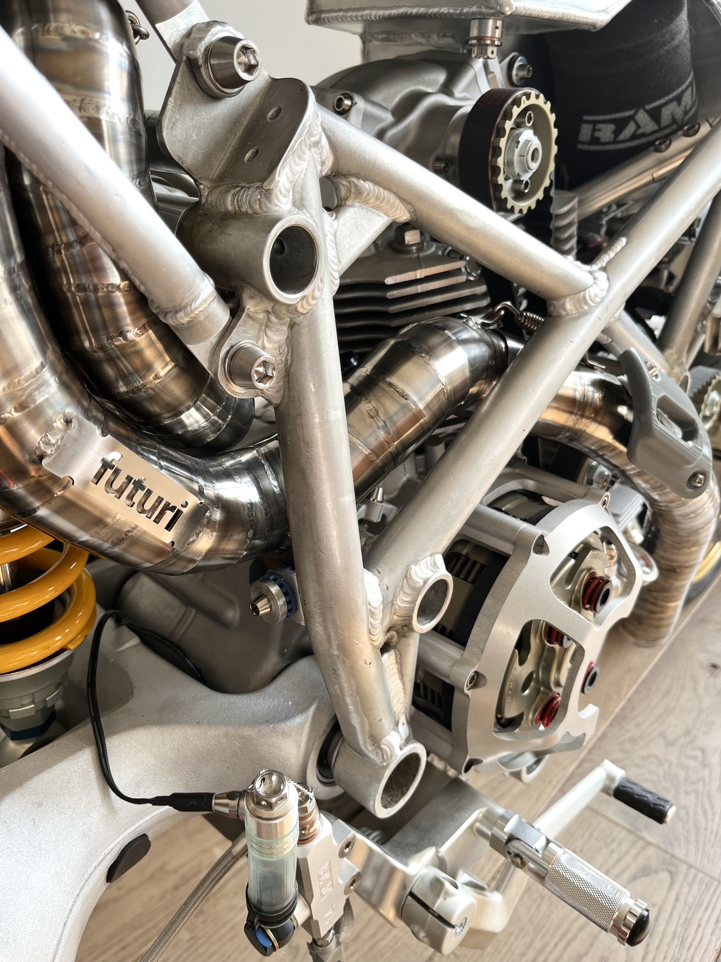
EXHAUST VALVES
Exhaust valves done! At least the valves itself. The manual actuation and position locking of the valves will be added later (parts are on the way).
Why? Here in the Netherlands the police isn’t super happy with extremely loud bikes. So I wanted a method to reduce exhaust noise on the fly when needed. This is my solution. I know it works because I have used this method on multiple other bikes.
It was a major challenge getting these valves in under the subframe, because the exhaust runs were getting a bit long and space was running out. With some trial and error I was able to fit everything in.
More on the actuation later!
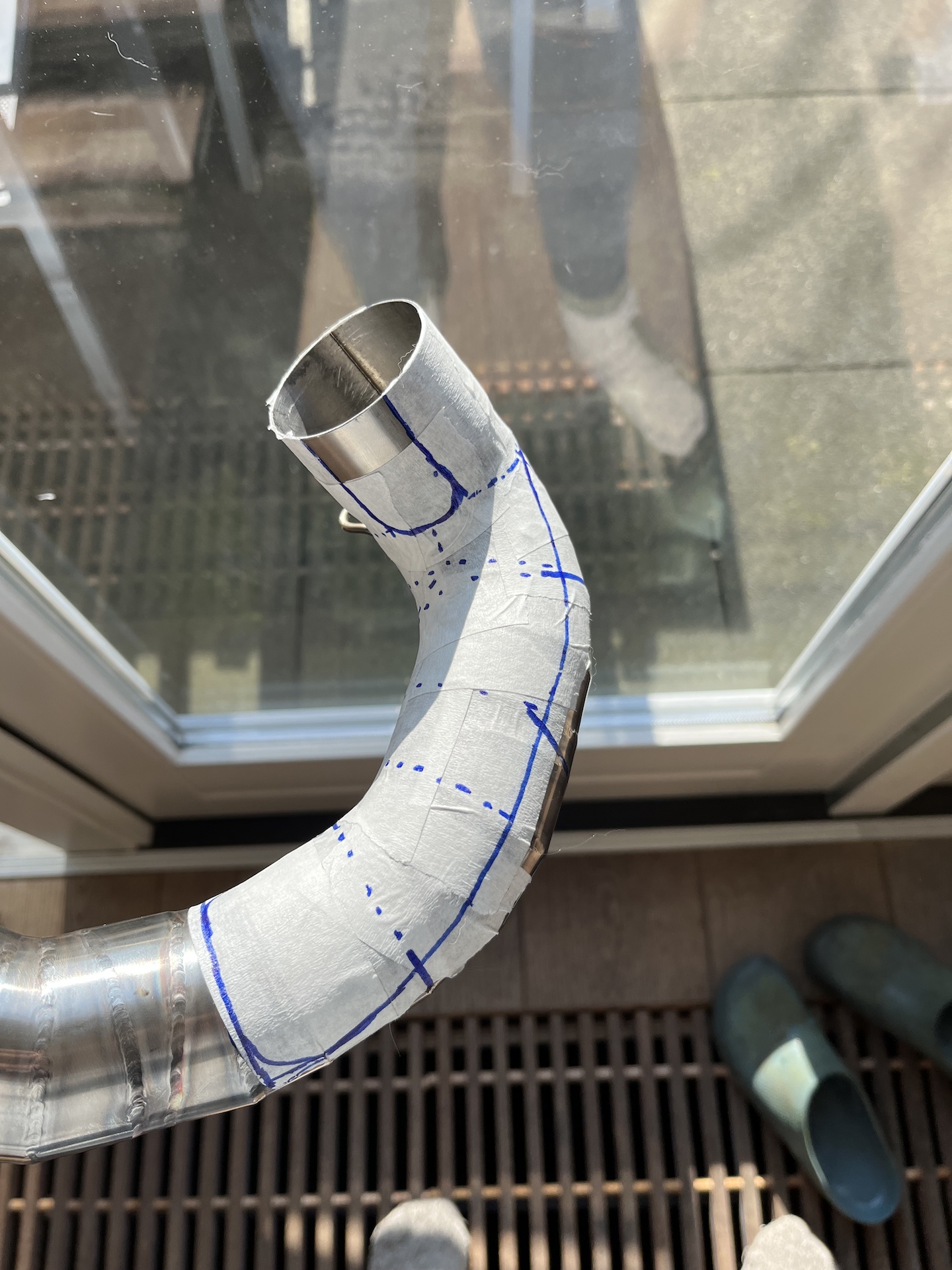
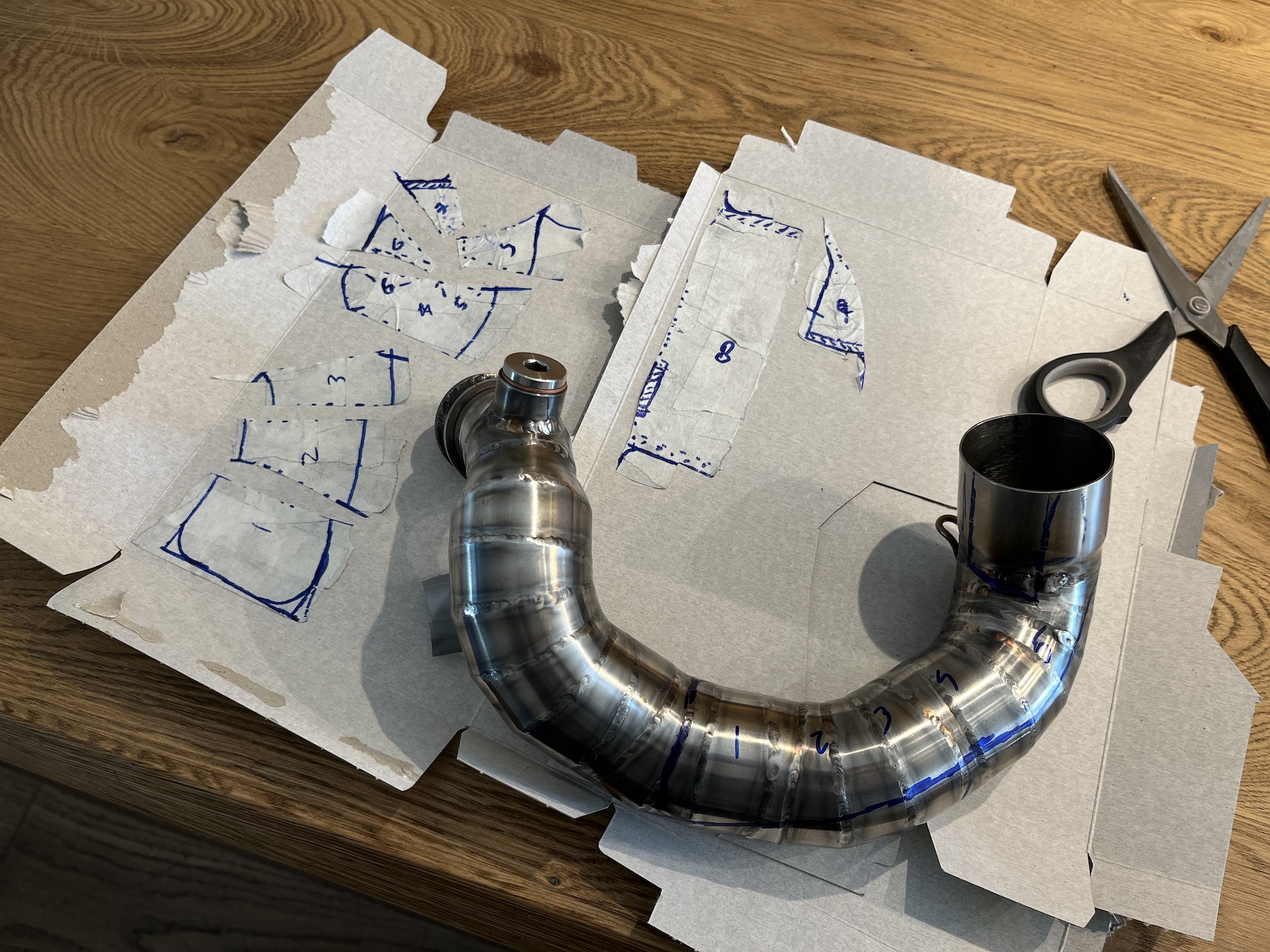
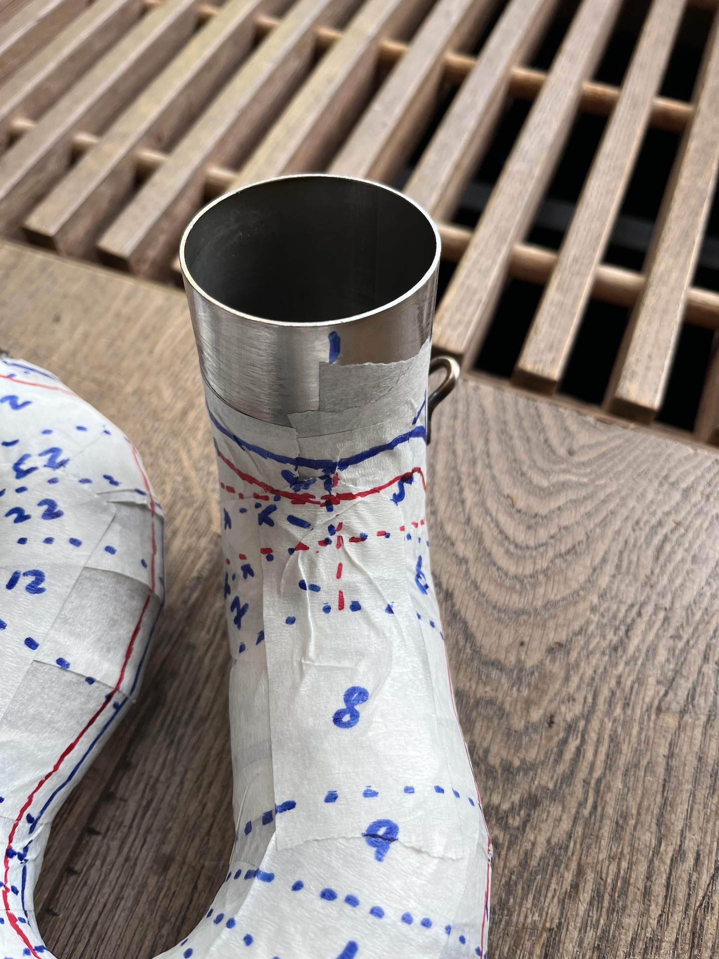
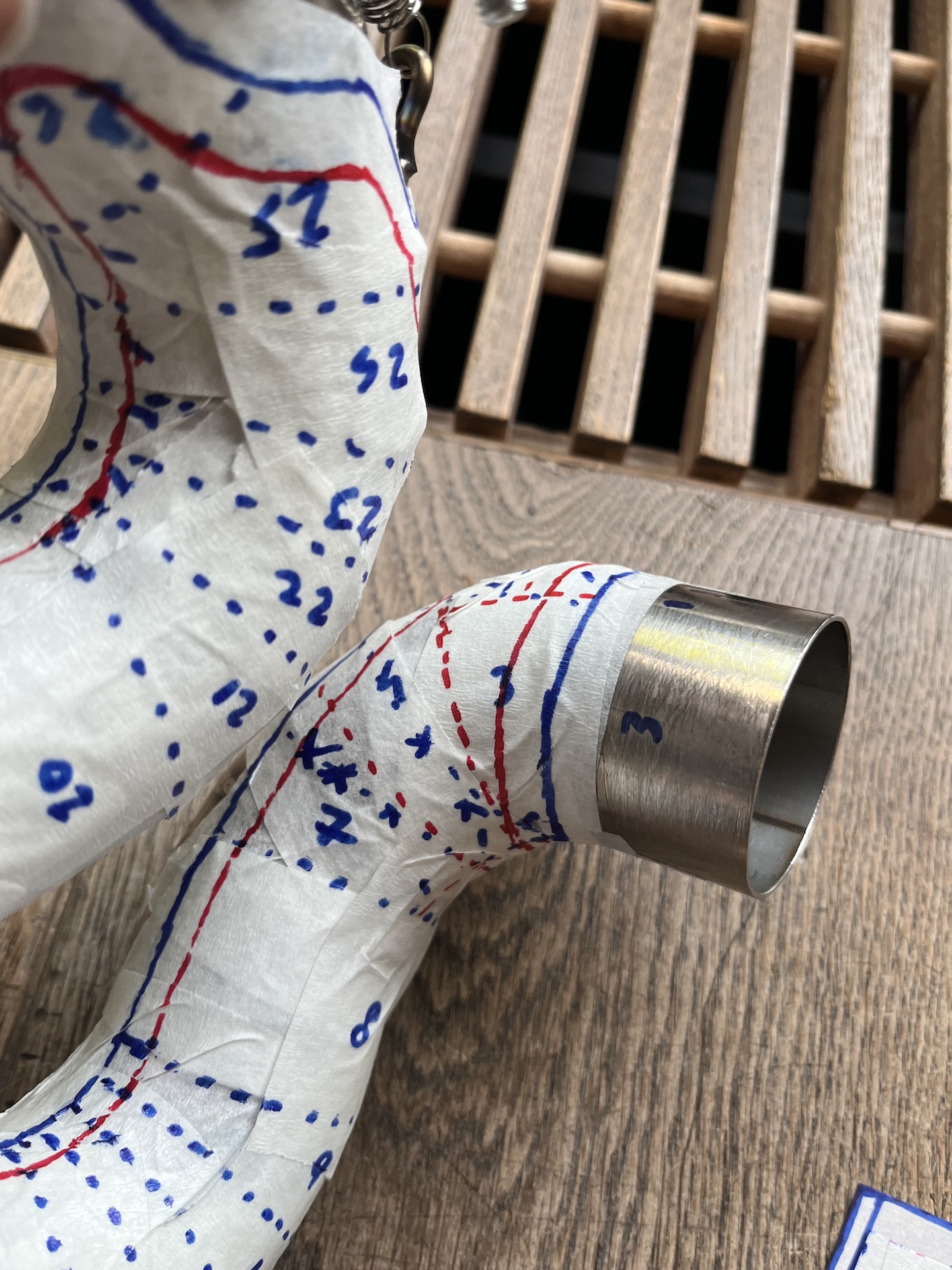
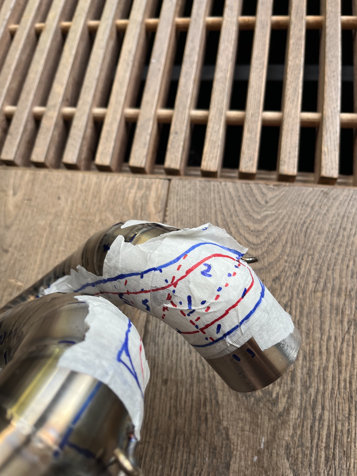
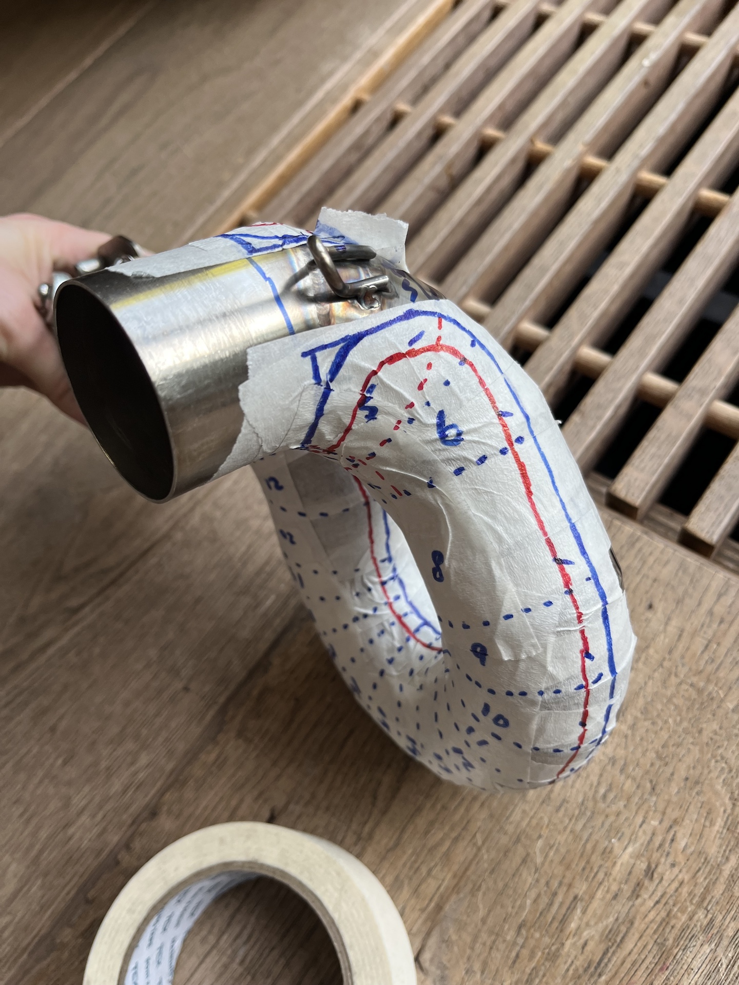
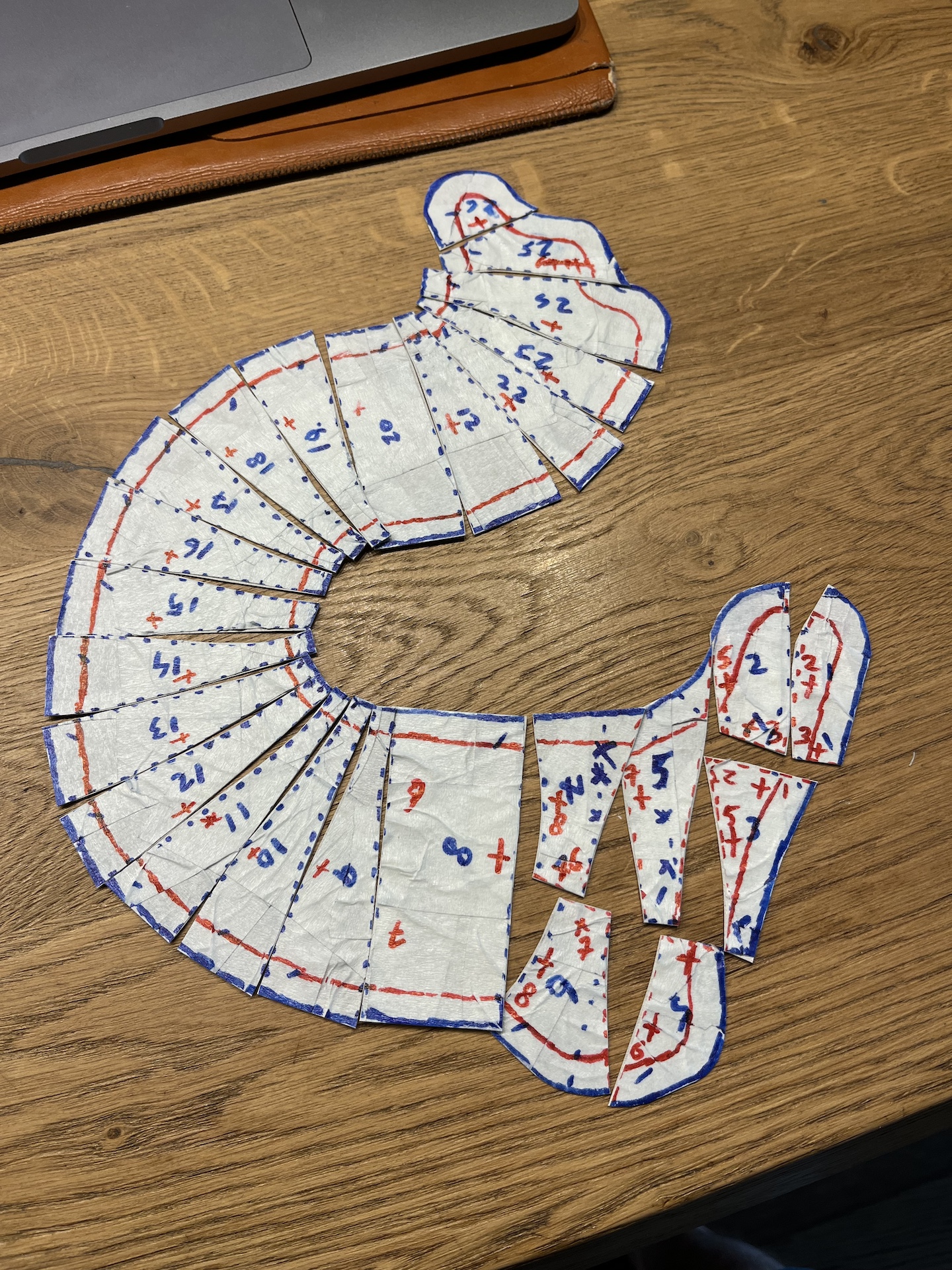
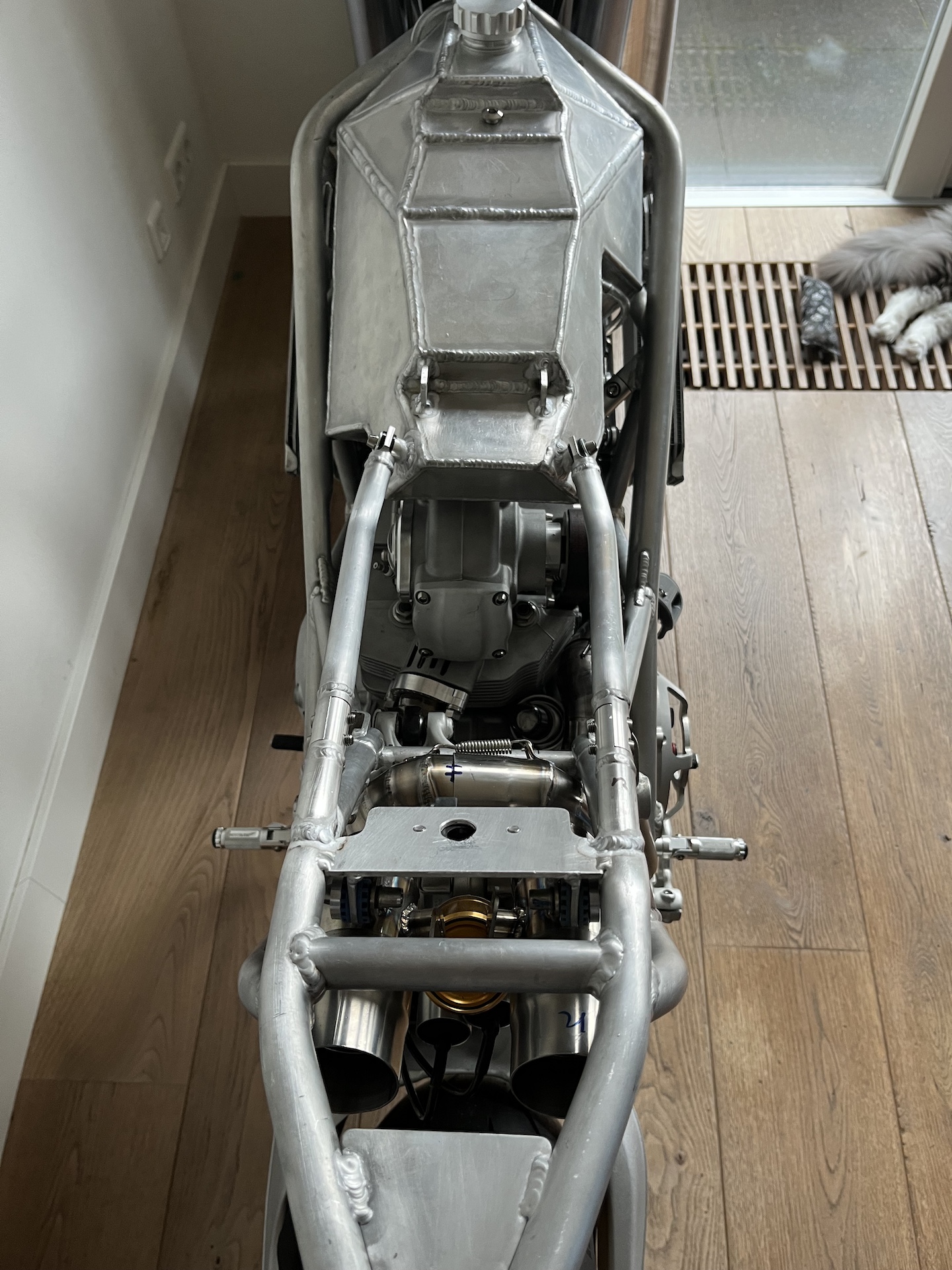
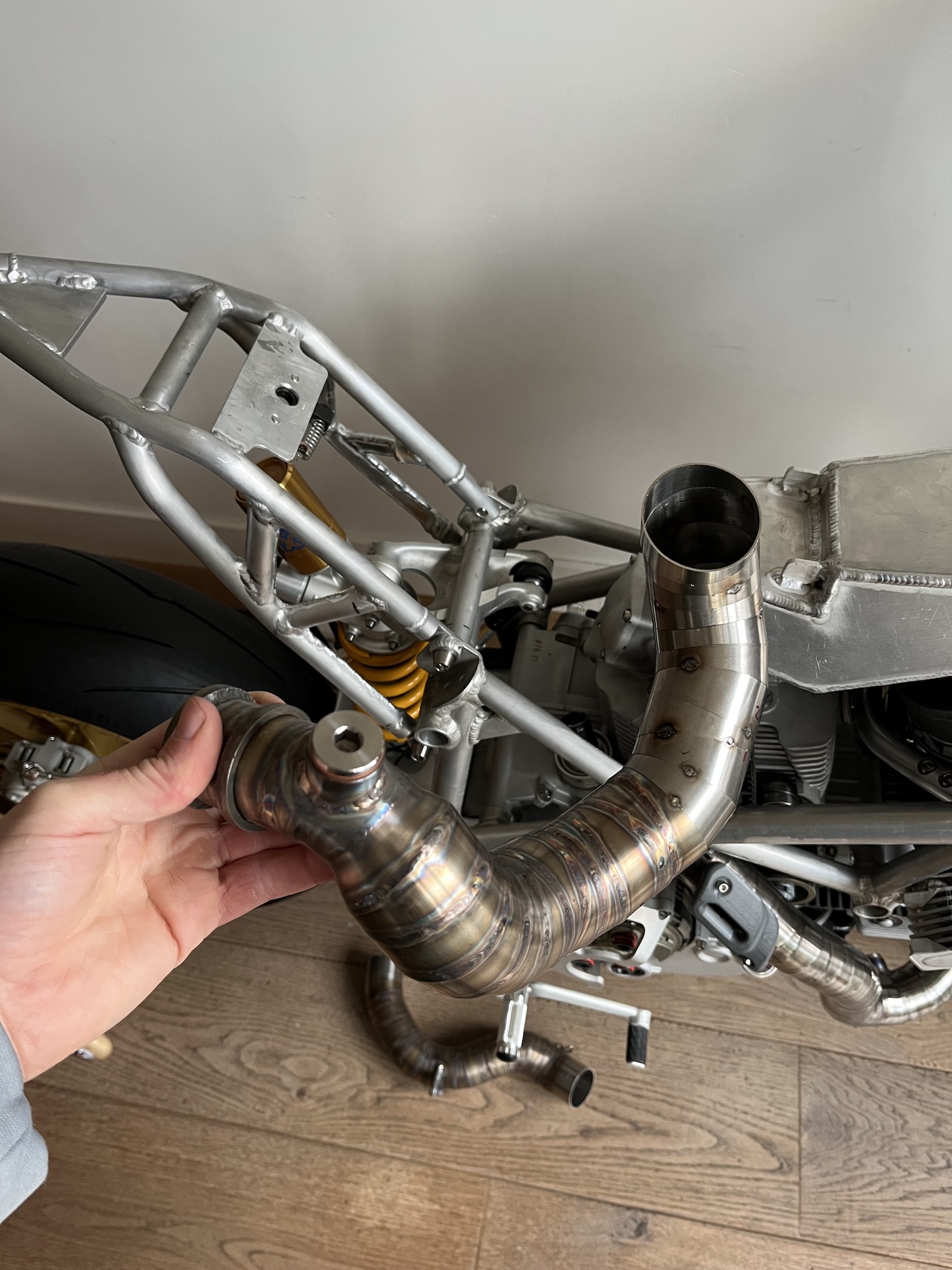
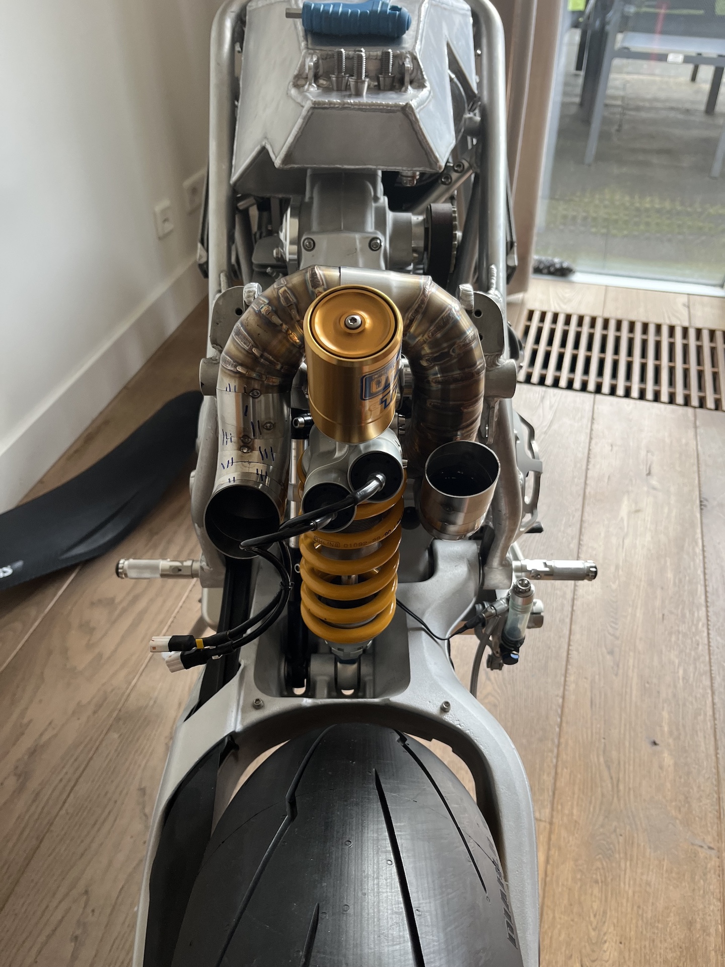
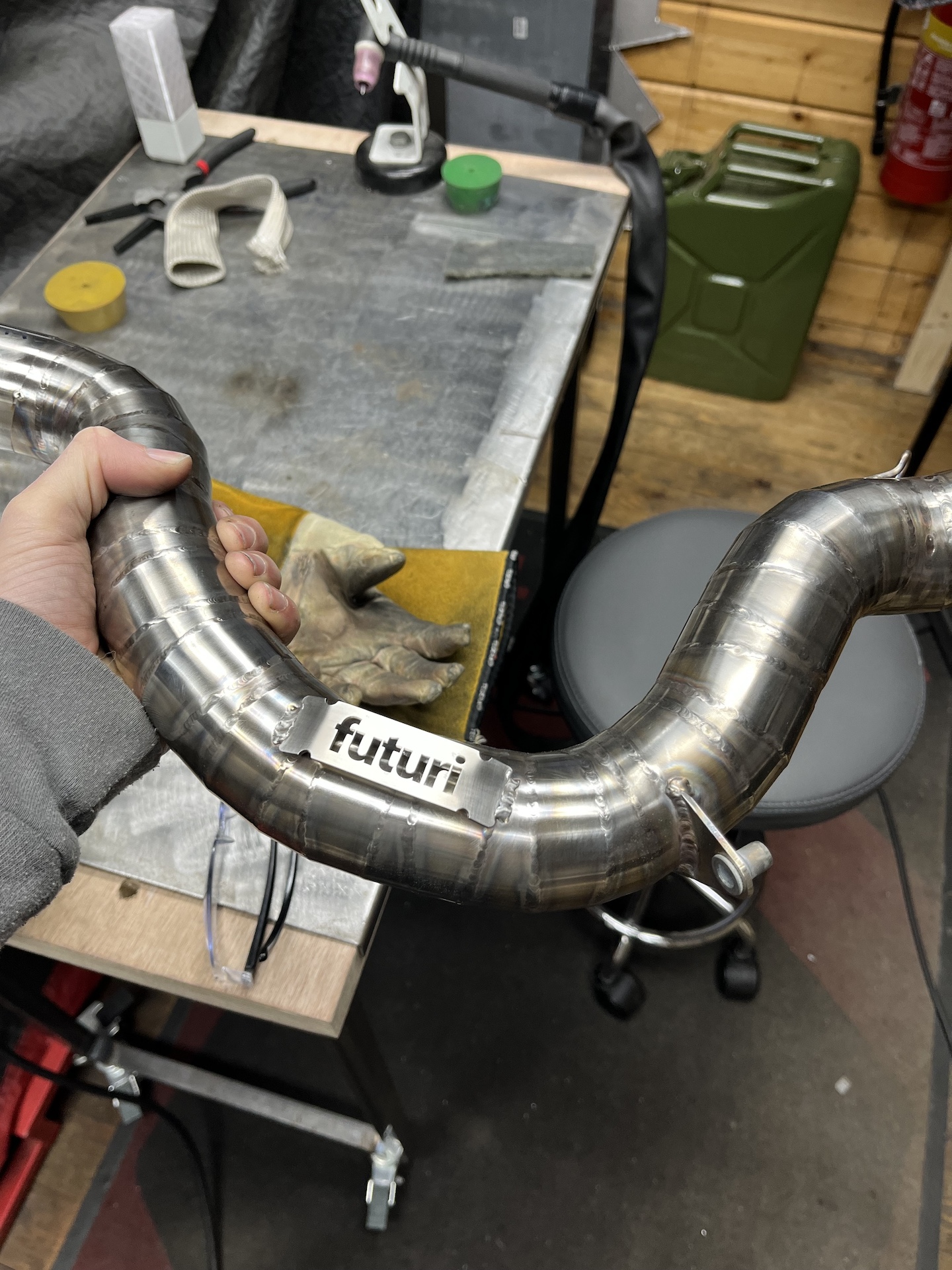
FINALIZING THE EXHAUST
Time to get that exhaust planned out and welded up! It’s 98% finally! I know the exhaust is still really close, but allot of heat shielding needs to be installed to make sure the shock doesn’t get cooked. I get allot of responses on how this setup will break the rear shock. I know in this current config it will die within 5 min, but please trust me. I have a plan with the heat shielding! More on that in the future!
Why the weird bend? I want both headers to be roughly the same length for the best performance and sound (taking into consideration the pressure difference because of the sharp bends). Will be adding a balancing pipe later on.
These 3d printed pie-cut mockup pieces I designed have made my life so much easier building an exhaust system like this.
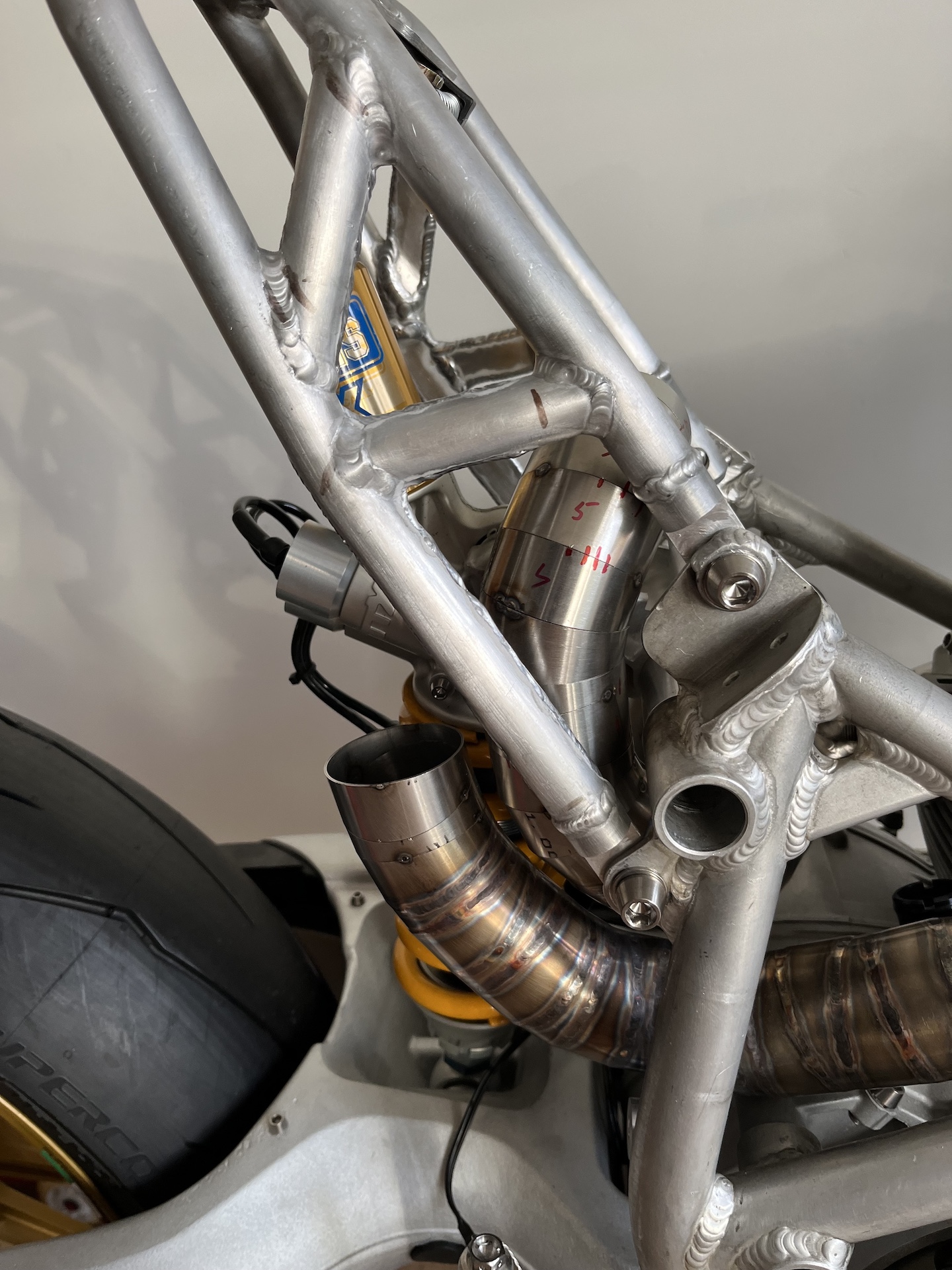
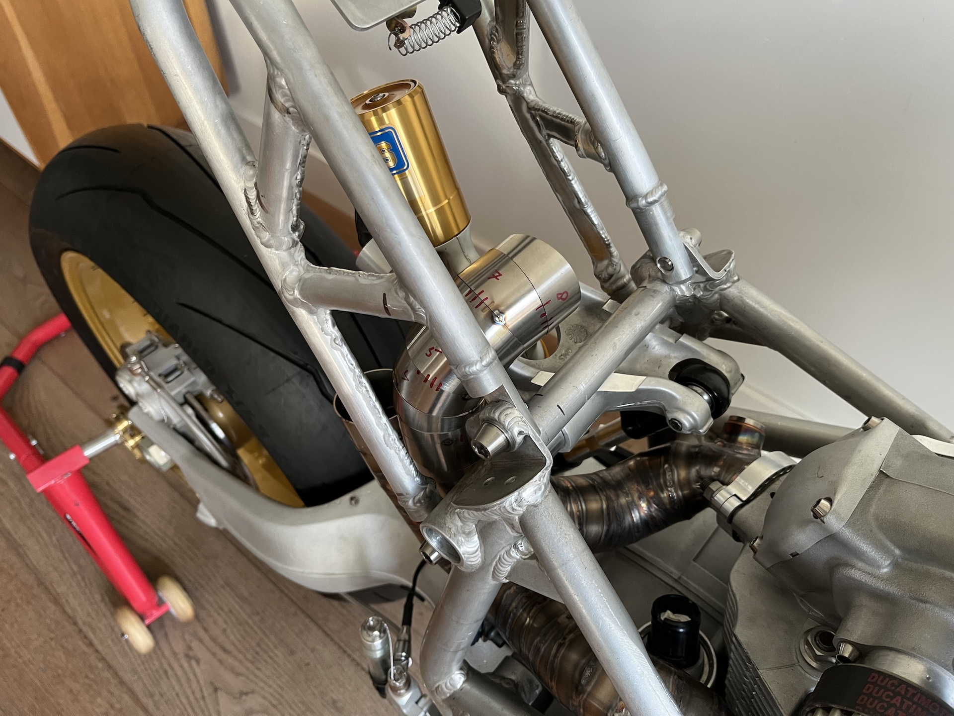
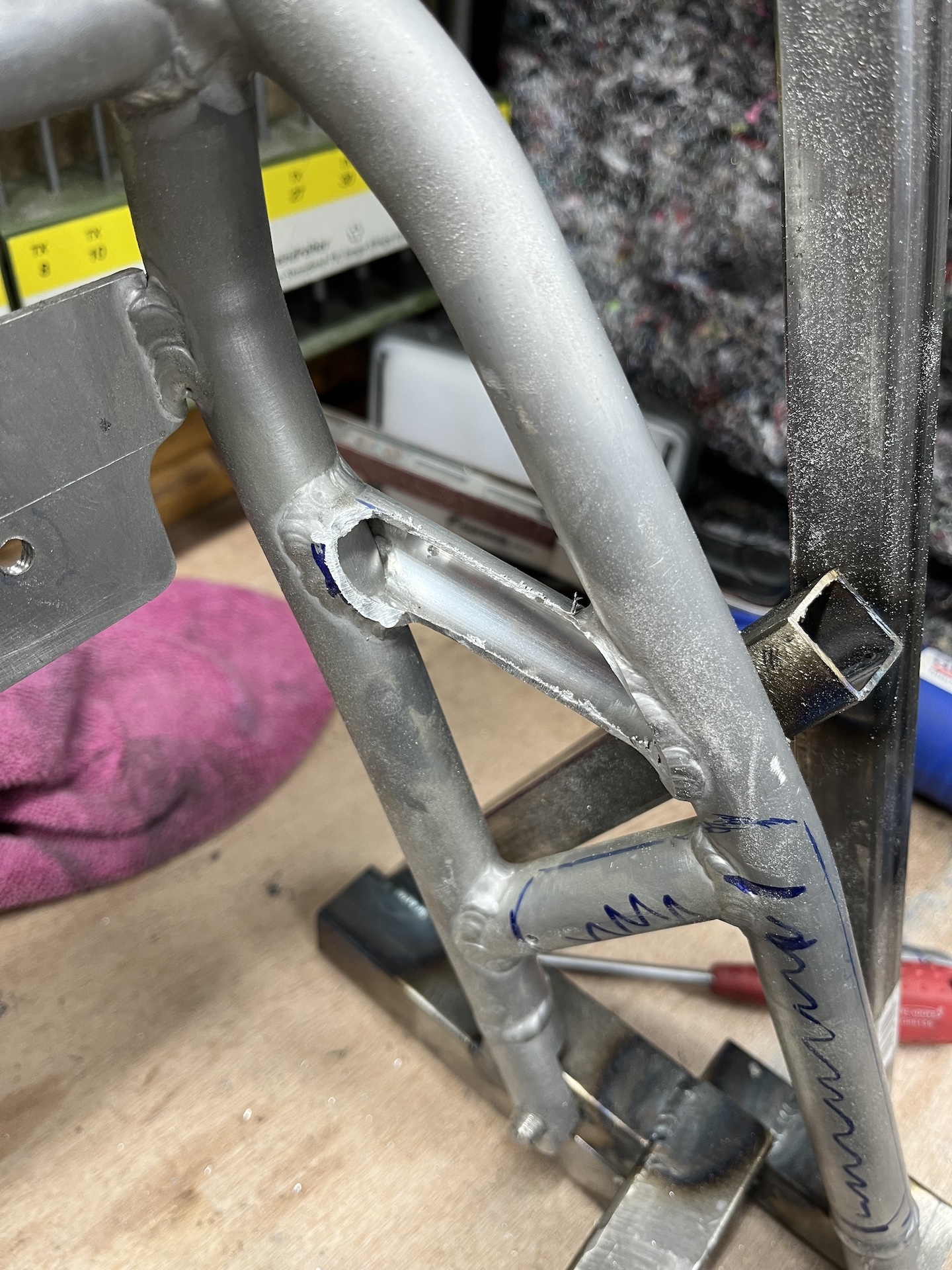
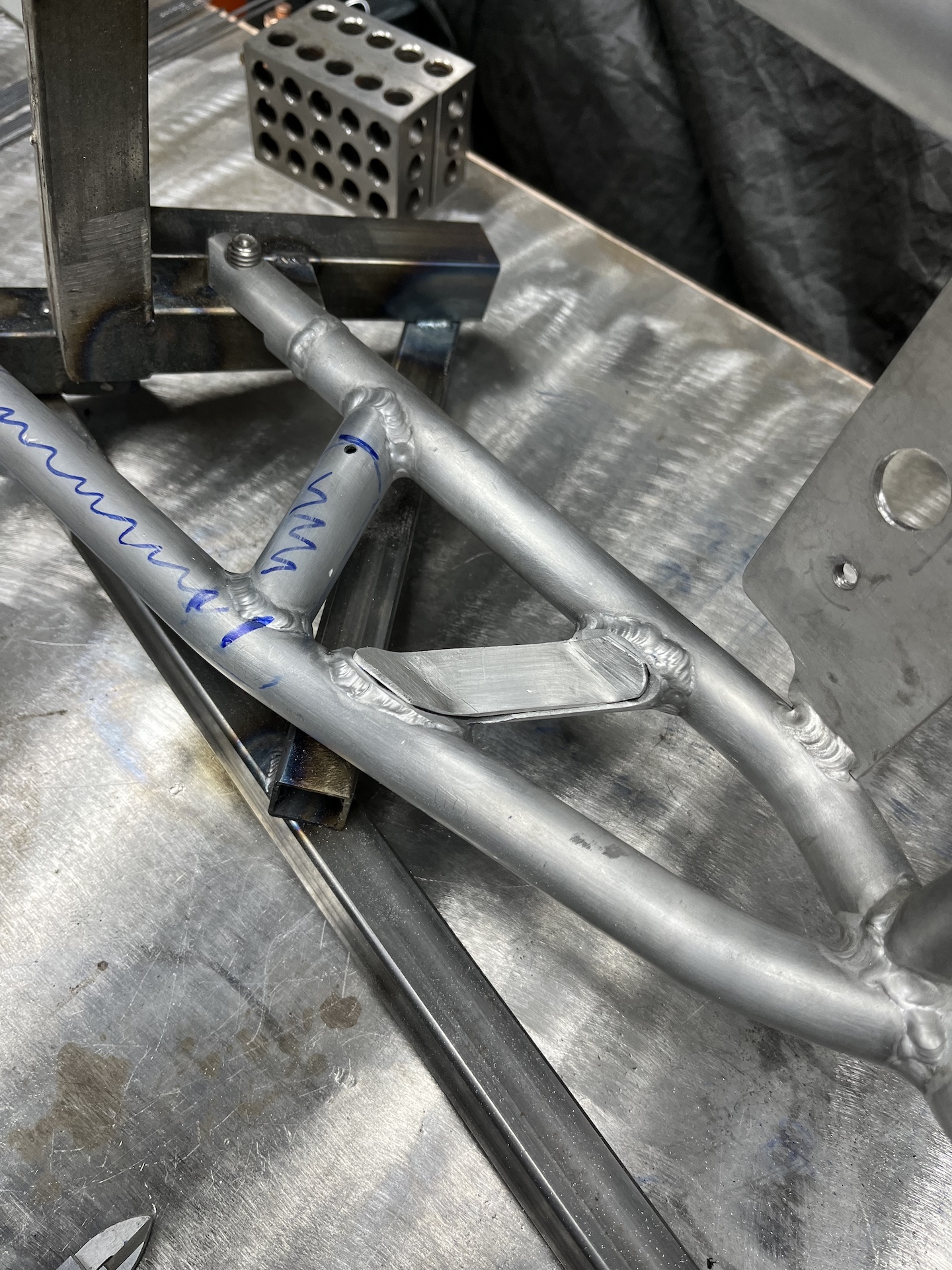
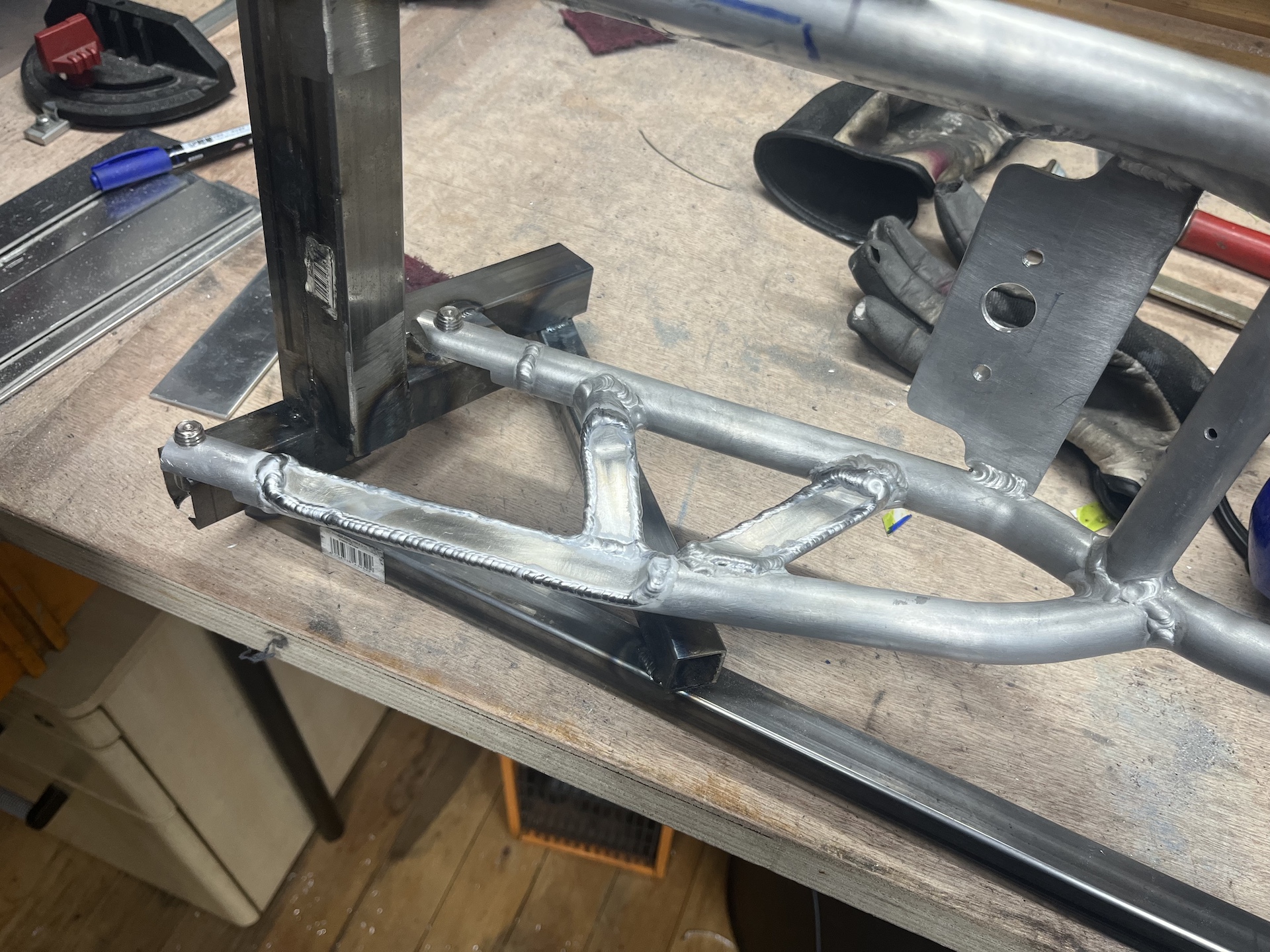
NOTCHING THE SUBFRAME
k here we go. Going to cut up that aluminium subframe I spend so much time on. It needs to be noticed out on the inside on both sides. The exhaust is going to run so extremely close to the rear shock that I need to create extra space, every mm counts!
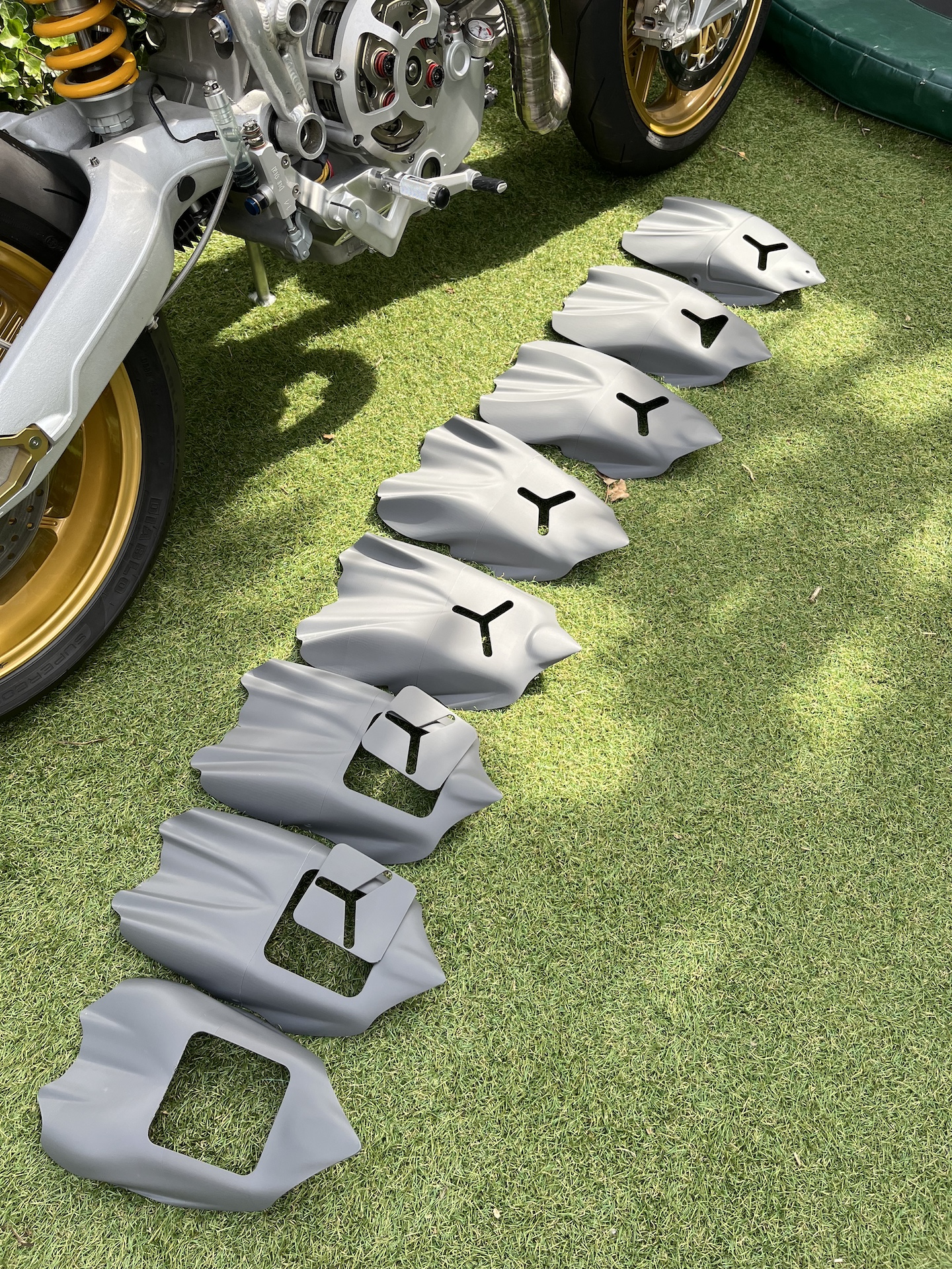
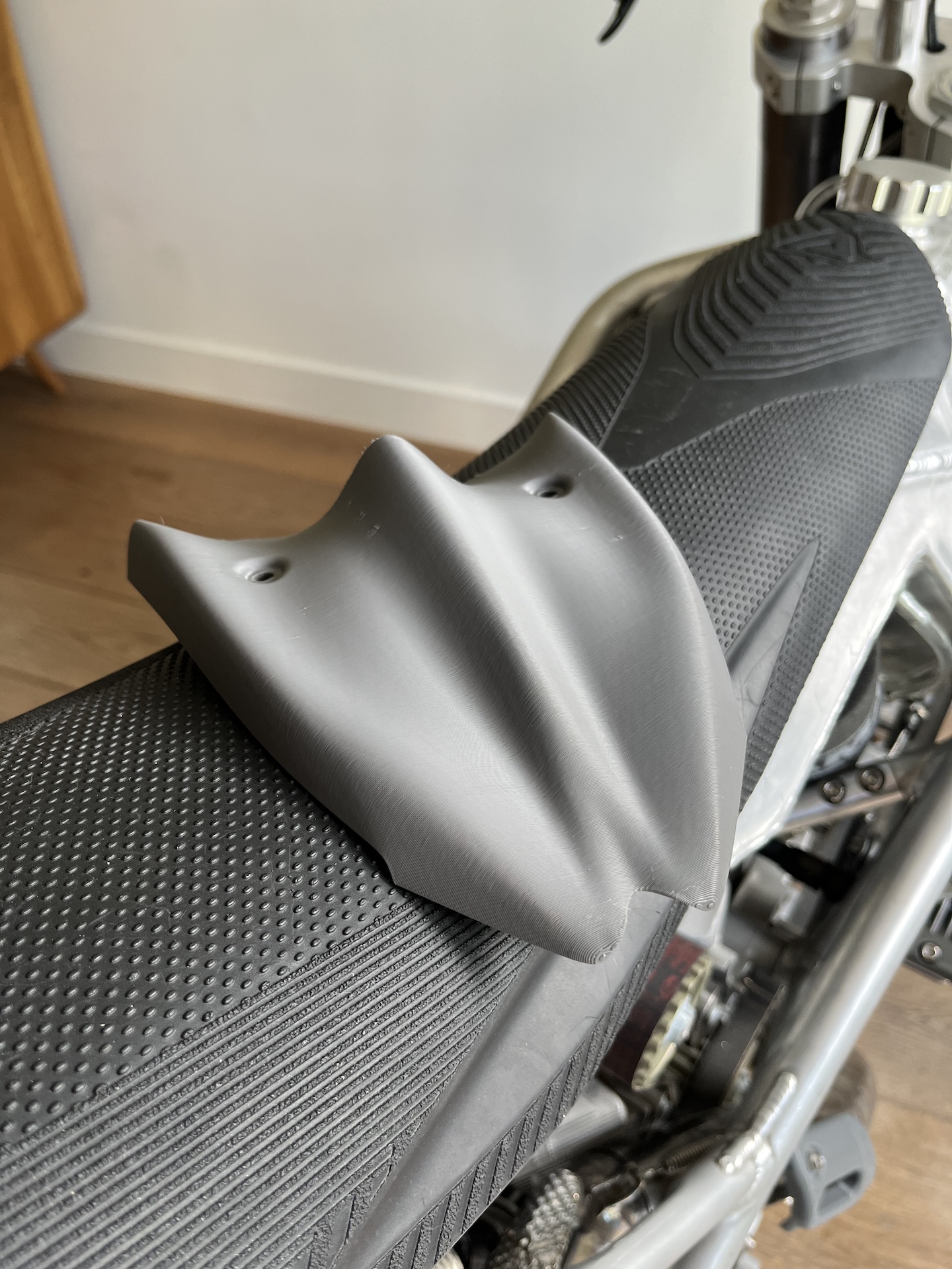
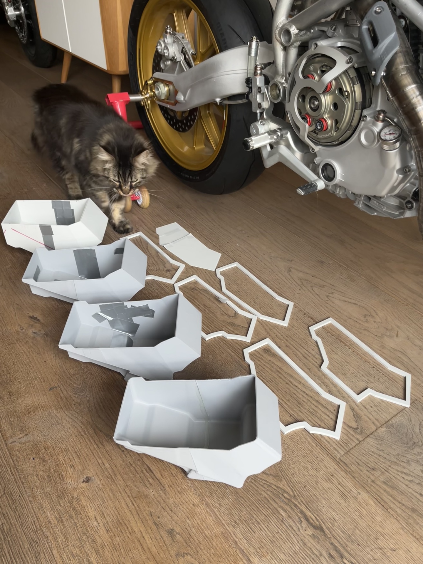
3D PRINTED FAIRING DESIGN PROCESS
In some time I will be making all the fairings out of carbon fiber. However I first need to make molts to allow that fabrication. To make sure everything is going to look exactly how I want, and to be able to make quick design changes I started designing all the fairings in CAD and 3D printing them. Wow, this is such a cool method to validate design choices.
Also when printing in the correct material I am able to build molds directly from these prints. Again speeding up the whole fabrication process.
Please note all the designs in in progress. The front fender is extremely hard to design and get right. As you can see I am not at design number 3 or 4 I think. And probably will need a few more iterations before I get to a point that I like.